Components and Functions (Theory)
5-4 LOGIQ V2/LOGIQ V1 – Basic Service Manual
5610739-100 English Rev.10
Block Diagram
System Diagram
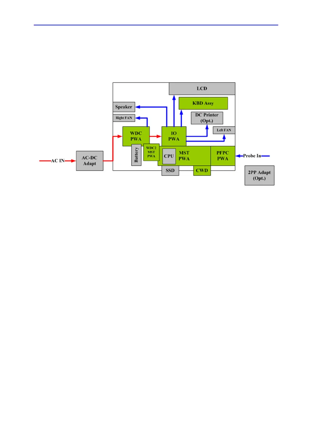
Figure 5-1. LOGIQ V2/LOGIQ V1 System Block Diagram
Introduction
AC-DC adapter provides DC power input to WDC PWA.
WDC PWA is main power supply for the system, it provides multi
powers to MST PWA and IO PWA.
MST provides the main control function, 64 channels
transmitting/receiving and related signal processing, and
connects to CWD board.
IO board receives MISC signals from MST board and make
necessary processing, it provides multi-user interface (such as
HDMI, LAN, USB, S-Video etc.).
PFPC board shall transfer 64 channels to 128 channels for RS
type probe.
KBD Assy provides multi function keyboard.
2PP adapter shall expand the RS probe port quantity to two.