GE_UPS_ISG_LPS_3UL_20K_30K_2US_V010.docx
Installation Guide LP33 Series 20 & 30 UL S2
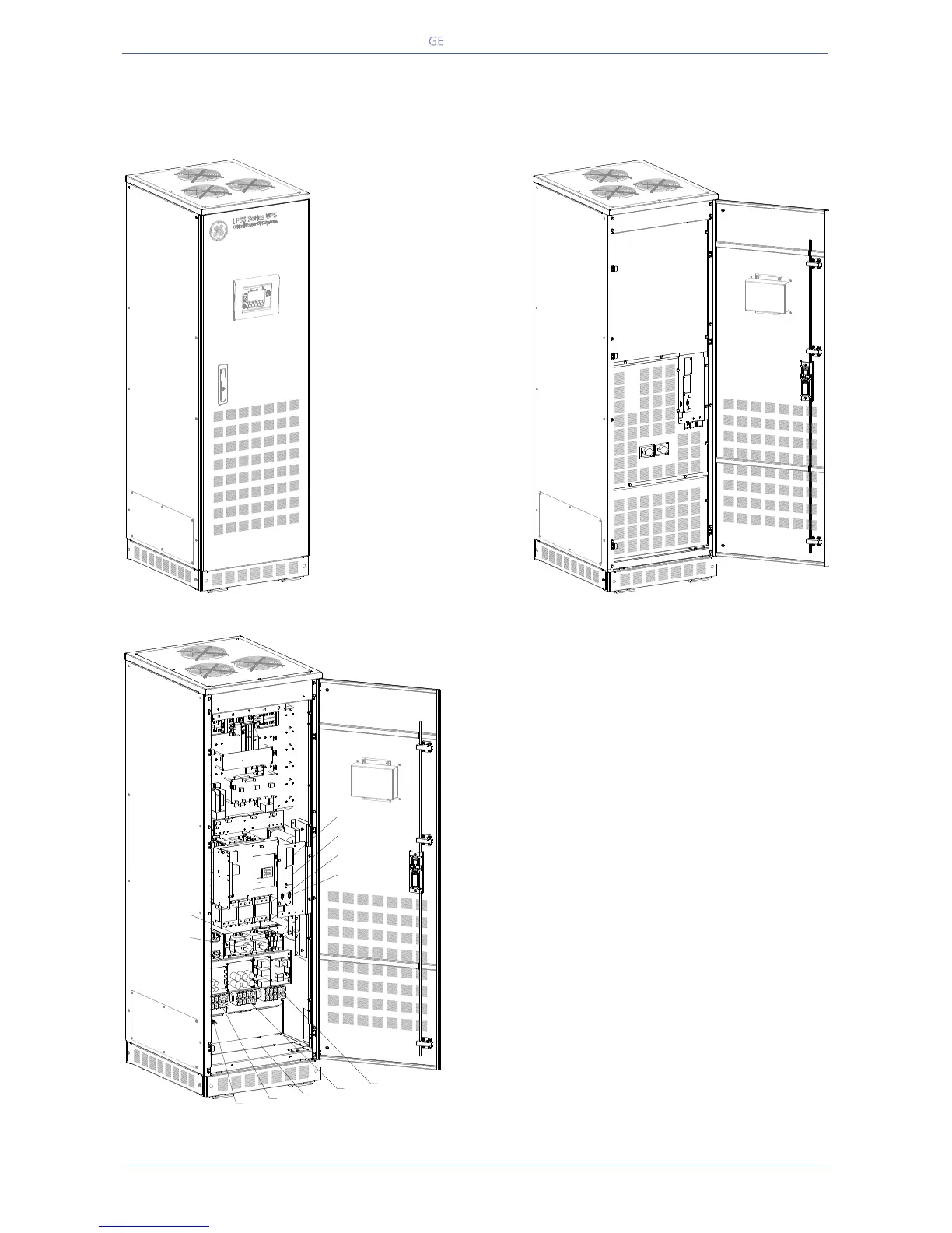
2 LAYOUT
2.1 LAYOUT LP33 SERIES 20 & 30
Fig. 2.1-2 General view with open door
Fig. 2.1-3 General view without protection panels
Opening for input and output of cables
Customer Interface Board (optional)
RPA parallel board (optional)
3-ph SNMP/WEB plug-in adapter (option)
Terminals for common mains input connection
(rectifier + bypass)
Terminals in case of dual mains input (optional)
Terminals for load output connection
Terminals for external battery connection
LPS33U_020-030_S2_UPS_GE_01
LPS33U_020-030_S2_UPS_GE_02
Q2
Q1
LPS33U_020-030_S2_UPS_GE_03
SNMP
CI
RS232
RC
SNMP
CI
RS232
RC
Q1
Q2
X1
X4
1
X2
X3

 Loading...


