GE_UPS_ISG_LPS_3UL_20K_30K_2US_V010.docx
Installation Guide LP33 Series 20 & 30 UL S2
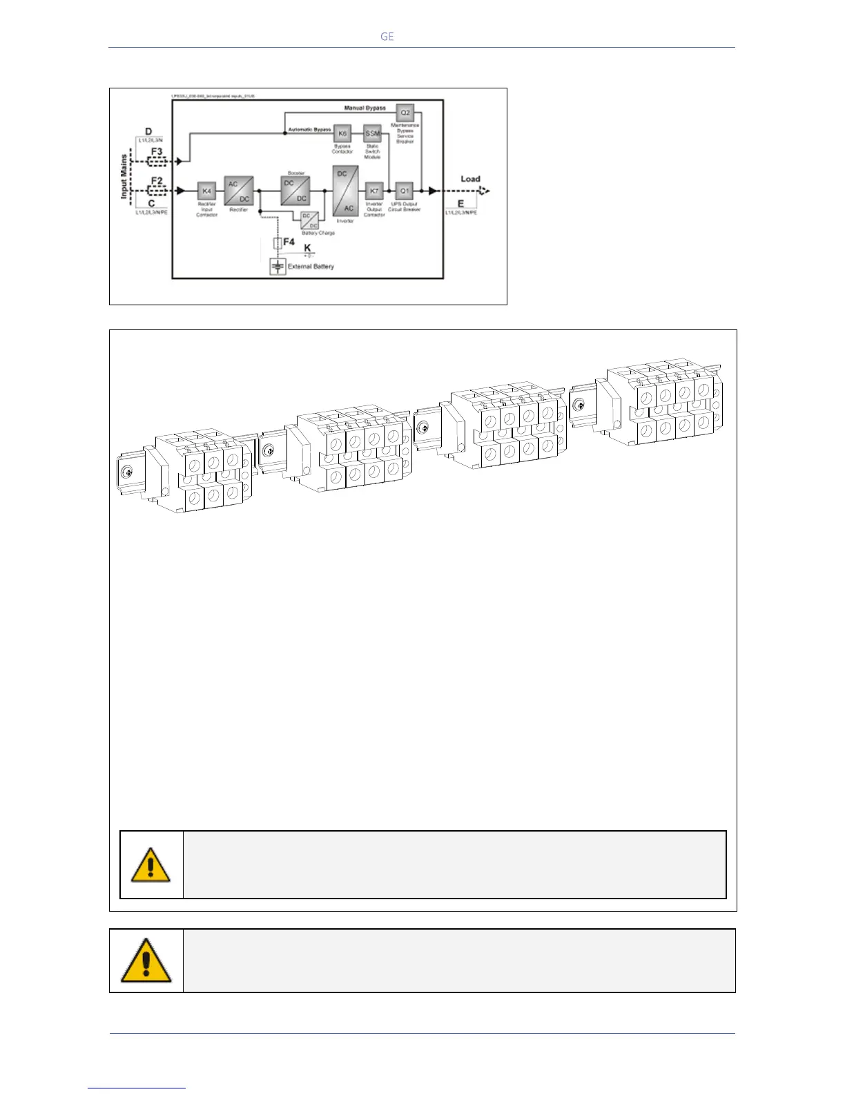
4.9.2 Dual input utility (option)
Fig. 4.9.2-1 Dual input utility (option)
Dual input utility
On request, the UPS can be
delivered for dual input utility.
Two independent lines (F2 and F3)
supply separately the rectifier and
the bypass inputs
With this configuration, when the
rectifier-input fuses are opened, the
automatic bypass and the
maintenance bypass are supplied
by the other line.
Fig. 4.9.2-2 Terminals for dual input utility
X1 Mains 1 - Rectifier input utility connection
L1-1 = Rectifier Phase A
L2-1 = Rectifier Phase B
L3-1 = Rectifier Phase C
N1 = Mains Neutral
PE = Main Ground
X2 Mains 2 - Bypass input utility connection
L1-2 = Bypass Phase A
L2-2 = Bypass Phase B
L3-2 = Bypass Phase C
N = Mains Neutral
X3 Load - Output load connection
L1 = Load Phase A
L2 = Load Phase B
L3 = Load Phase C
N2 = Load Neutral PE = Load Ground
Connect wire to the terminals by using
appropriate tools and appropriate torque shown
in Section 4.8.1.
Max. rating X1, X2 , X3 and X4 terminals:
NOTE !
For UPS correct operation, the input utility phase rotation must be clock-wise.
Inside the UPS, all neutrals N1 and N2 are connected together.
NOTE !
This UPS is designed to operate in a wye-configured electrical system with a solidly
grounded neutral.
LPS33U_030-040_Connection separate_02US
Utility 1
X4
Battery
Load
X1
X3
L1-1
L2-1
L3-1
N1
PE
L1
L2
L3
N2
PE
-
0
+
PE
Utility 2
X2
L1-2
L2-2
L3-2
N

 Loading...


