4.8.1 Power connections
Input/output and DC connections are provided with terminal blocks.
Please refer to chart below for torque specifications.
Carefully read the following recommendations before proceeding:
Ensure that the AC and DC external isolators are OFF and locked to prevent their inadvertent
operation.
Do not close any external isolators prior the commissioning of the equipment.
The preferred power cable entry location for installation purposes is from the bottom right side of
the UPS (see Fig 4.8.1-1).
For cable entry from the bottom remove the cover plate and provide for a suitable isolated
protection cover.
The input/output cables must be connected in clockwise phase rotation for both Bypass and
Rectifier Input Terminals if separate, taking care to avoid risk of short circuit between different
poles.
The grounding and neutral connection of the electrical system must be in accordance with local
regulations.
In case of additional cabinets containing batteries, input/ output transformers, etc, their ground
terminals must be connected to the UPS main ground terminal.
Once the power cables have been connected, re-install the internal safety shields and close the
cabinets by re-installing all external panels.
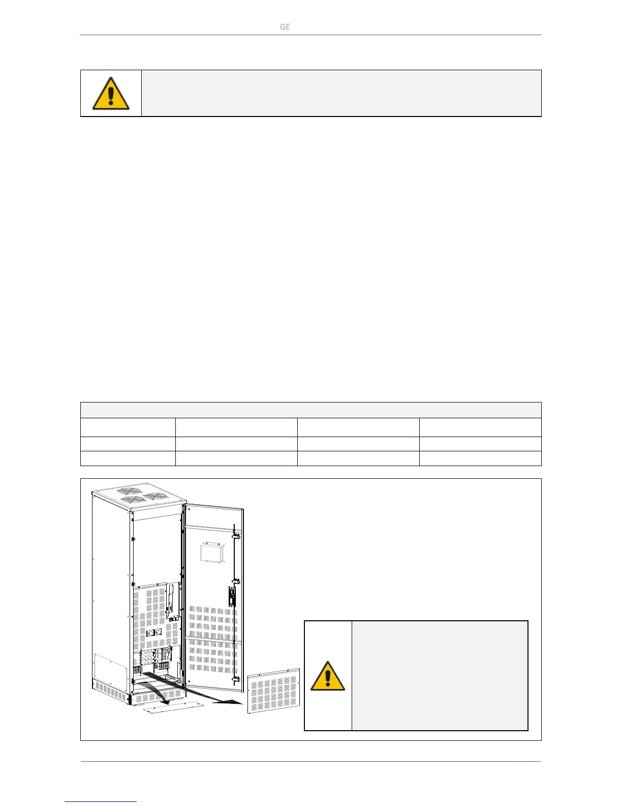
Access to the terminals and instructions for
bottom feed cable connections
To access Input, Output and Battery connections
proceed as follows:
Open the front door “A” of the cabinet.
Remove the protection panel “B”.
Remove the bottom fascia cover “C” and drill
holes in bottom cover as needed.
NOTE !
For bottom feed applications, drill
appropriate holes in plate “C” for
cable conduits (max. 4 x 2”).
Please remove the plate “C” before
drilling any holes.
See Fig 4.8.1-1 - details “C”.

 Loading...


