GE_UPS_ISG_LPS_3UL_20K_30K_2US_V010.docx
Installation Guide LP33 Series 20 & 30 UL S2
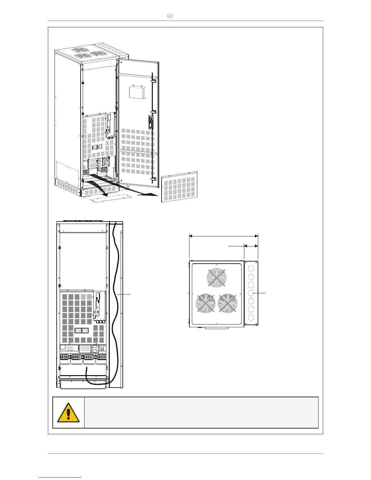
Access to the terminals and instructions for top feed cable connections
Fig. 4.8.1-2 Access to the input / output connections
To access input, output and battery
connections proceed as follows:
Open the front door “A” of the cabinet.
Remove the protection panel “B”.
Remove the bottom fascia cover “C”.
Rout cable through side channel cable
entry.
Use appropriate knockout in top cover shown
above.
Route cable through side channel as shown on
left.
NOTE !
For top feed applications, knock out appropriate holes in side channel cover for
cable conduits. See Fig 4.8.1-2
C
A
B
LPS33U_020-030_S2_Connection_TEC_01
Q2
Q1
LPS33U_020-030_S2_Connection_TEC_Front_01
TOP FEED
AC ROUTING
LPS33U_020-030_S2_Connection_TEC_Top_01
7X KNOCKOUTS
FOR " CONDUIT
29.66"
753.4m
6.04"
153.4m

 Loading...


