GE_UPS_ISG_LPS_3UL_20K_30K_2US_V010.docx
Installation Guide LP33 Series 20 & 30 UL S2
5.4 CUSTOMER INTERFACE BOARD (OPTION)
WARNING !
The installation and cabling of the options must be performed by
QUALIFIED SERVICE PERSON.
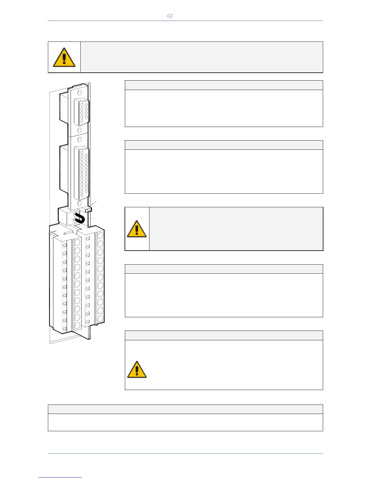
Fig. 5.4-1 Customer Interface
C = Common
NO = Normally Open
NC = Normally Closed
Serial port J3 - RS232 (sub - D - female 9 pin)
Total remote management of the system using
software GE Power Diagnostics, GE Data Protection or
GE Service Software for system protection and
management of the UPS systems.
Pin 2: TX (out)
Pin 3: RX (in)
Pin 5: GND
J2 (sub – D female 25p) – Output signals on voltage-free contacts
Signals on terminals X1 and on connector J2 are in parallel and
therefore not separated galvanically from each other.
The programmable signals on X1 and J2 will be disabled with Q1
open, with the exception of the signals for:
16 – Manual bypass ON
24 – Relay output ON
25 – Relay output OFF
26 – EPO
X1 – Output signals on voltage-free contacts
X2 – Terminals EPO connection (Emergency Power Off)
EPO (Emergency Power Off)
To enable this function, remove jumper JP3 on the Customer
Interface and the cable on the terminal X2 / 1, 2.
(See Fig. 5.4-1).
Verify if the cable on the terminal X7 / 1, 2 and jumper JP8 on the
P2 – Mainboard are OFF (see Fig. 5.4-3).
Programmable functions on input contacts
Programmable / Generator ON (NO)
LPS33U_Customer interface_01
1
2
3
4
5
6 7 8 9
10
11
1615
14
13
12
2221
201918
17
J3
J2
X1
21
JP3
X2

 Loading...


