GE_UPS_ISG_LPS_3UL_20K_30K_2US_V010.docx
Installation Guide LP33 Series 20 & 30 UL S2
4.4 PLACE OF INSTALLATION
The UPS should be installed in a restricted area where only qualified personnel should be admitted.
The place of installation should be clean, dust-free, and provided with proper ventilation or air-
conditioning.
Verify for sufficient floor load capacity (see Section 4.1.1).
We strongly advice that the ambient temperature should not exceed 68° - 77°F / 20° - 25°C (max. 104°F
/ 40°C). See Section 4.5.
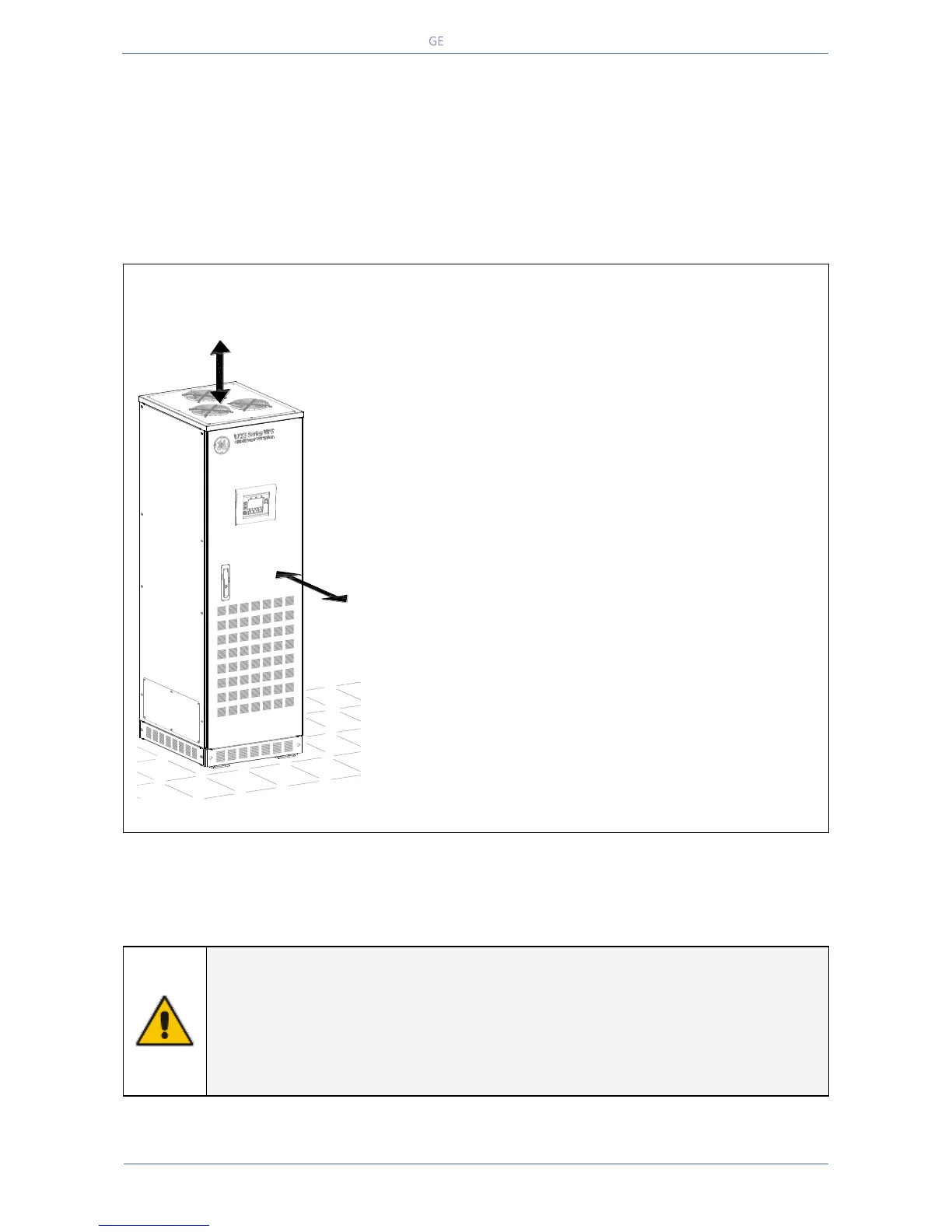
Positioning of the UPS LP33 Series 20 & 30
Fig. 4.4-1 Positioning LP33 Series 20 & 30
The rear panel of the UPS may be mounted flush to a
wall or other structure.
Clearance around the front of the unit should be
sufficient to enable free passage of personnel with the
doors fully open, and to allow sufficient airflow to the
door vents.
To guarantee proper cooling air exhaust, the
recommended minimum clearance between ceiling
and top of the UPS is 16” (400mm).
Battery cabinets must be placed beside the left side of
the UPS cabinet.
A single-phase power outlet (208Vac) should be
provided near the UPS for connection of power tools,
test equipment or connectivity devices.
This outlet must be grounded.
The LP33 Series 20 & 30 UPS can radiate radio frequency energy.
Although some RFI (Radio Frequency Interference) filtering is inherent to the UPS there is no guarantee that
the UPS will not influence sensitive devices such as cameras and monitors that are positioned close by.
If interference is expected, the UPS should be moved away from the sensitive equipment.
NOTE !
Operating temperature is very important for valve regulated battery (maintenance
free).
Operation at temperatures higher than 68°F (20°C) will reduce life expectancy.
Follow the recommendations of the battery supplier and other local standards.
The installation and cabling of the battery must be done by qualified people.
Min.
16" / 400mm
LPS33U_020-030_S2_UPS disposition_GE_01
Min.
32" / 800mm

 Loading...


