GE_UPS_ISG_LPS_3UL_20K_30K_2US_V010.docx
Installation Guide LP33 Series 20 & 30 UL S2
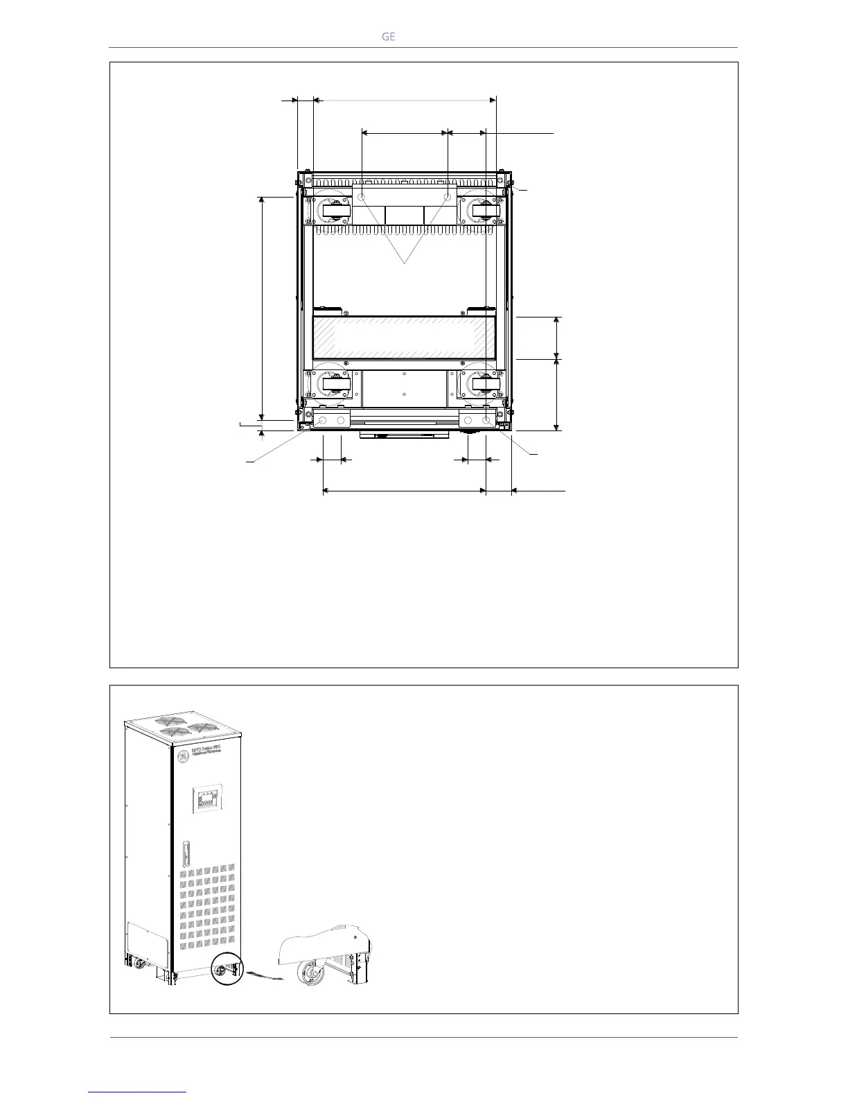
Opening for input and output cable connections LP33 Series 20 & 30
Fig. 4.4-2 Opening on the bottom of the cabinet for input and output cables
LP33 Series 20 & 30 opening is provided on the bottom of the UPS for the connection of input and
output cables.
Pay attention to the position of this opening, when choosing the placement of the UPS.
The UPS cabinet is free standing and normally does not require to be bolted to the floor.
The UPS cabinet can be fixed however to the floor by bolting it to the floor with provided seismic
brackets in the anchor locations show.
Positioning of the UPS cabinet
Fig. 4.4-3 Bolts for stabilizing the cabinet
LP33 Series 20 & 30 is equipped with wheels for
easy placement of the UPS.
To make the UPS movable on wheels, the bolts
on each leg of the cabinet have to be turned
counter-clockwise, until they are free from the
floor and thus the cabinet supported on wheels.
After having positioned the UPS at its final
location, the cabinet has to be secured by
rotating the bolts on each leg clockwise, but the
wheels must still touch the floor.
LPS33U_020-030_S2_UPS view bottom_01
Front
ANCHOR LOCATIONS
9.50"
241.3mm
4.25"
107.9mm
18.0"
457.2mm
2.81"
71.4mm
Ø 0.75"
Ø19.05mm
2.00"
50.8mm
2.00"
50.8mm
Ø 0.75"
Ø19.05mm
4.96"
126mm
7.70"
195.5mm
20.16"
512mm
1.73"
44mm
24.56"
623.7mm
4X LIVELLING FEET
ANCHOR LOCATIONS
BOTTOM CABLE ENTRY
AREA 100 SQ IN (64500 SQ mm
ANCHOR LOCATIONS
1.14"
28.9mm
LPS33U_020-030_S2_UPS wheels_GE_01

 Loading...


