GE_UPS_ISG_LPS_3UL_20K_30K_2US_V010.docx
Installation Guide LP33 Series 20 & 30 UL S2
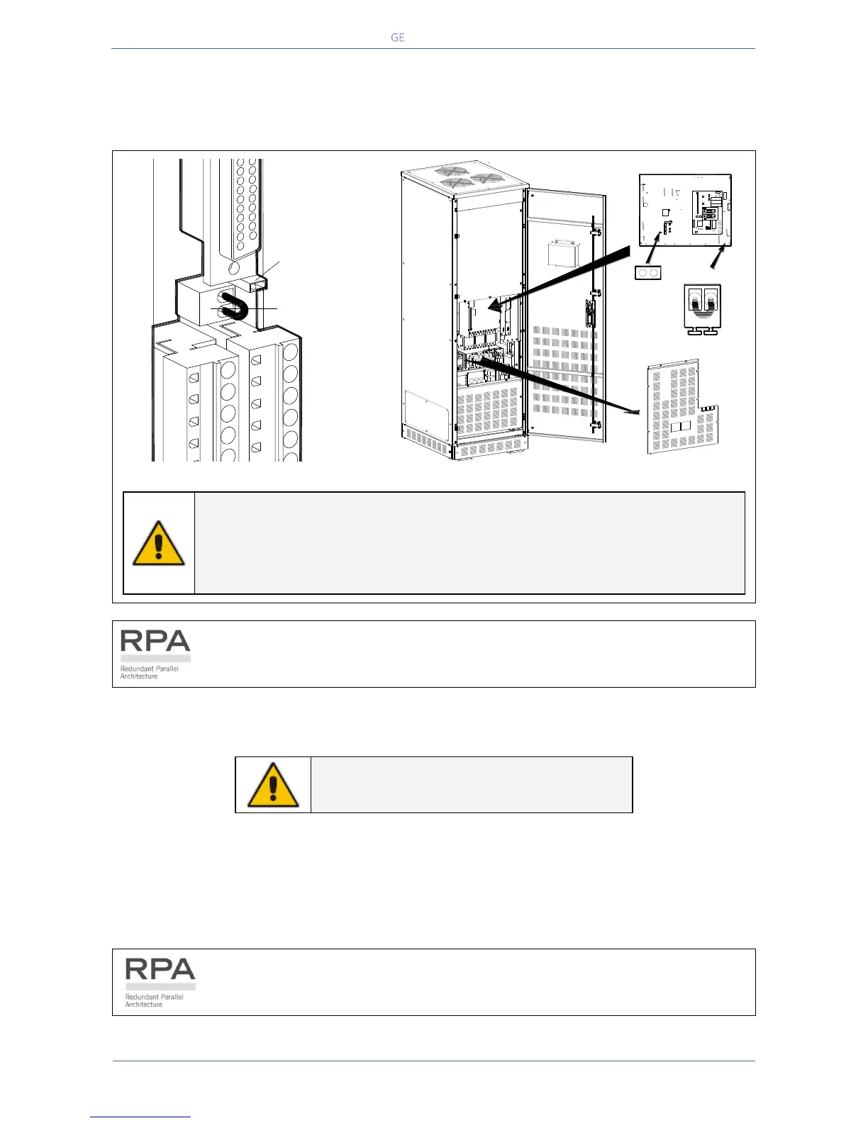
EPO (Emergency Power Off)
An external Emergency switch (NC - Normally Closed voltage-free contact) can be connected on
terminals X2 / 1, 2 or connector J2 / 12, 25 of the Customer Interface (see Fig. 5.4-1 / X2 & J2).
Fig. 5.4-2 PCB Customer Interface
Fig. 5.4-3 PCB P1 – Control board
NOTE !
To enable this function, remove jumper JP3 on the Customer Interface and the
cable on the terminal X2 / 1, 2 (see Fig. 5.4-2).
Verify if the cable on the terminal X7 / 1, 2 and jumper JP5 on the P1 – Control
board are OFF (see Fig. 5.4-3).
In a Parallel System a separate NC (Normally Closed) contact must be connected
individually to each unit.
When activated, this switch causes the immediate shut-down of booster, battery-charger, inverter; and
the contactors K4, K6 and K7.
NOTE !
This procedure could imply a load shut-down.
When the EPO has been activated, the system must be restored as follows:
Press the push-button EPO (contact on X7 / 1, 2 is closed again).
Press the key “O” (Inverter OFF – see Section 6.2 of User Manual) on the control panel.
Press the key “I” (Inverter ON – see Section 6.2 User Manual) on the control panel.
In case of a Parallel System press the key “O” (Inverter OFF) on the control panel of
each unit connected on the parallel bus and having its output switch Q1 closed.
SGT4000_customer interface_01
1 2
3
4
5
6 7
8 9 10
11
1615
14
13
12
2221201918
17
J3
J2
X1
21
JP3
X2
1 2
P1 - Control board
JP5
X7
LPS33U_020-030_S2_UPS-X7-JP5_01

 Loading...


