1–4 350 FEEDER PROTECTION SYSTEM – INSTRUCTION MANUAL
DESCRIPTION OF THE 350 FEEDER PROTECTION SYSTEM CHAPTER 1: INTRODUCTION
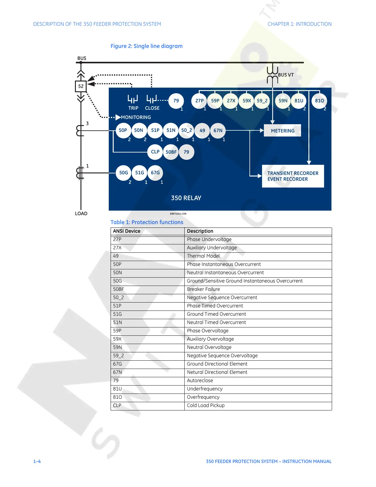
Figure 2: Single line diagram
Table 1: Protection functions
898742A1.CDR
350 RELAY
TRIP
BUS
LOAD
3
1
52
CLOSE
50G/
51G
50P 50N
79
50G 51G
22
21
METERING
TRANSIENT RECORDER
EVENT RECORDER
51N51P
50_2
111
49
1
1
27P
59P 27X 59X 59_2 59N 81U 81O
CLP
50BF 79
11111 12 2
MONITORING
BUS VT
67N
67G
1
1
ANSI Device Description
27P Phase Undervoltage
27X Auxiliary Undervoltage
49 Thermal Model
50P Phase Instantaneous Overcurrent
50N Neutral Instantaneous Overcurrent
50G Ground/Sensitive Ground Instantaneous Overcurrent
50BF Breaker Failure
50_2 Negative Sequence Overcurrent
51P Phase Timed Overcurrent
51G Ground Timed Overcurrent
51N Neutral Timed Overcurrent
59P Phase Overvoltage
59X Auxiliary Overvoltage
59N Neutral Overvoltage
59_2 Negative Sequence Overvoltage
67G Ground Directional Element
67N Netural Directional Element
79 Autoreclose
81U Underfrequency
81O Overfrequency
CLP Cold Load Pickup
Courtesy of NationalSwitchgear.com
 Loading...


