CHAPTER 6: SETPOINTS S5 INPUTS/OUTPUTS
350 FEEDER PROTECTION SYSTEM – INSTRUCTION MANUAL 6–143
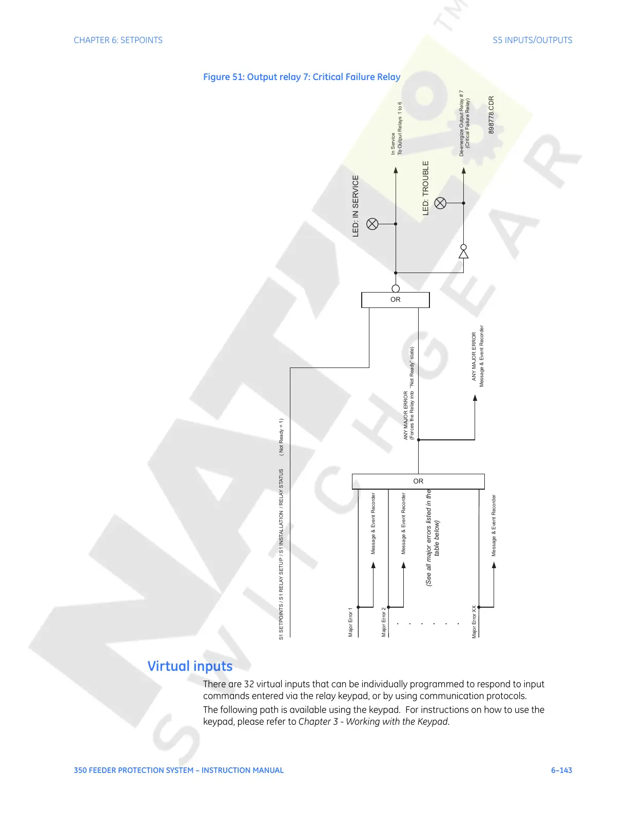
Figure 51: Output relay 7: Critical Failure Relay
Virtual inputs
There are 32 virtual inputs that can be individually programmed to respond to input
commands entered via the relay keypad, or by using communication protocols.
The following path is available using the keypad. For instructions on how to use the
keypad, please refer to Chapter 3 - Working with the Keypad.
ANY MAJOR ERROR
(Forces the Relay into “Not Ready” state
)
OR
S1 SETPOINTS / S1 RELAY SETUP / S1 INSTALLATION / RELAY STATUS
( Not Ready = 1)
LED: IN SERVICE
Message & Event Recorder
ANY MAJOR ERROR
OR
.
.
.
.
.
.
Message & Event Recorder
Message & Event Recorder
Message & Event Recorder
Major Error 1
Major Error 2
Major Error XX
(See all major errors listed in the
table below)
To Output Relays 1 to 6
In Service
De-energize Output Relay # 7
(Critical Failure Relay)
LED: TROUBLE
898778.CDR
Courtesy of NationalSwitchgear.com
 Loading...


