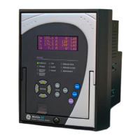
350C FEEDER PROTECTION SYSTEM – INSTRUCTION MANUAL
Table of Contents
1. INTRODUCTION Overview ................................................................................................................................1 - 1
Cautions and warnings ...................................................................................................1 - 2
Description of the 350 Feeder Protection System..............................................1 - 3
350 order codes..................................................................................................................1 - 6
Specifications.......................................................................................................................1 - 7
Password security....................................................................................................................1 - 7
Protection.....................................................................................................................................1 - 7
Metering........................................................................................................................................1 - 9
Data capture ..............................................................................................................................1 - 10
Control...........................................................................................................................................1 - 10
Inputs .............................................................................................................................................1 - 11
Outputs..........................................................................................................................................1 - 12
Power supply..............................................................................................................................1 - 13
Communications ......................................................................................................................1 - 13
Testing and certification .......................................................................................................1 - 14
Physical .........................................................................................................................................1 - 15
Environmental............................................................................................................................1 - 15
2. INSTALLATION Mechanical installation ...................................................................................................2 - 1
Dimensions..................................................................................................................................2 - 1
Product identification .............................................................................................................2 - 2
Mounting ......................................................................................................................................2 - 3
Unit withdrawal and insertion............................................................................................2 - 5
Electrical installation ........................................................................................................2 - 7
Terminal identification ...........................................................................................................2 - 8
Phase sequence and transformer polarity...................................................................2 - 10
Current inputs ............................................................................................................................2 - 11
Ground and sensitive ground CT inputs ........................................................................2 - 11
Zero sequence CT installation............................................................................................2 - 12
Voltage inputs............................................................................................................................2 - 13
Control power ............................................................................................................................2 - 13
Contact inputs ...........................................................................................................................2 - 14
Trip and Close output relays ...............................................................................................2 - 15
Serial communications..........................................................................................................2 - 17
IRIG-B .............................................................................................................................................2 - 18
3. INTERFACES Front control panel interface........................................................................................3 - 2
Description ..................................................................................................................................3 - 2
Display ...........................................................................................................................................3 - 3
Working with the Keypad....................................................................................................3 - 3
LED status indicators..............................................................................................................3 - 4
Relay messages ........................................................................................................................3 - 5
Target messages.....................................................................................................................3 - 5
Self-test errors..........................................................................................................................3 - 6
Flash messages.......................................................................................................................3 - 7
Software setup....................................................................................................................3 - 9
Quick setup - Software interface ......................................................................................3 - 9
EnerVista SR3 Setup Software............................................................................................3 - 9
Hardware and software requirements.........................................................................3 - 10
Courtesy of NationalSwitchgear.com

 Loading...


