CHAPTER 6: SETPOINTS S3 PROTECTION
350 FEEDER PROTECTION SYSTEM – INSTRUCTION MANUAL 6–85
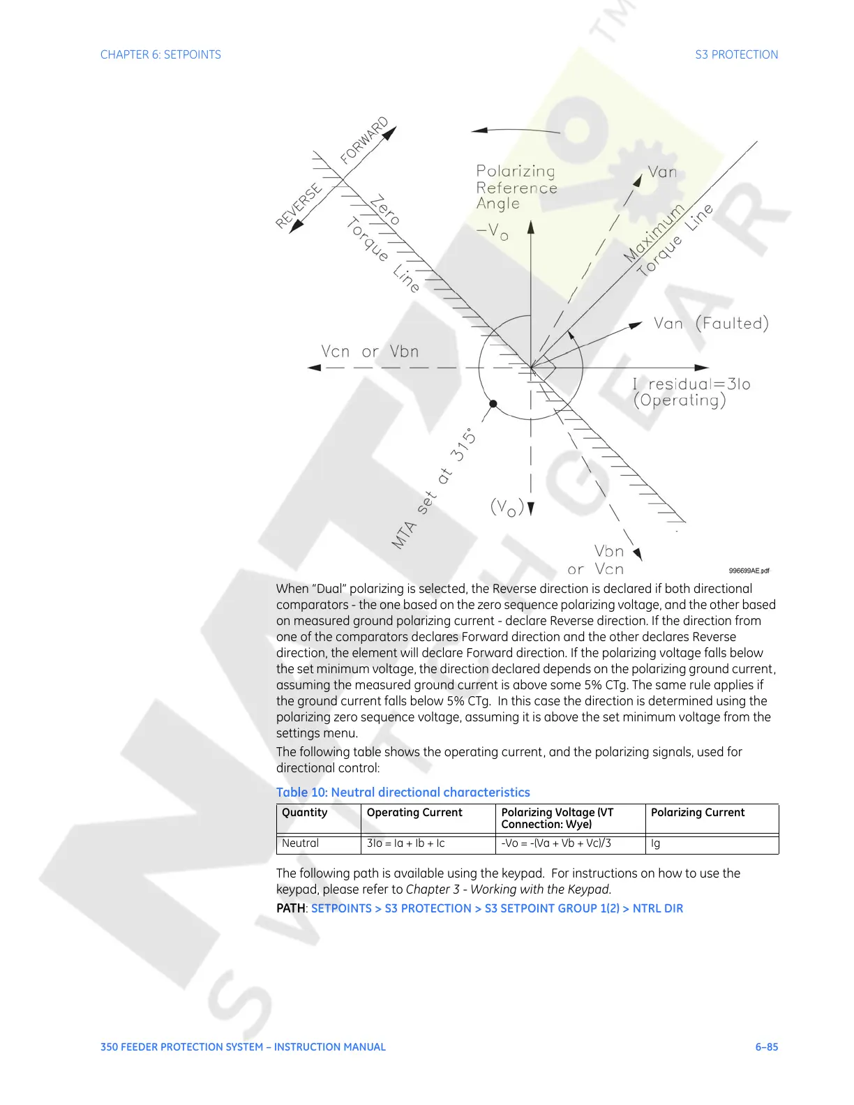
When “Dual” polarizing is selected, the Reverse direction is declared if both directional
comparators - the one based on the zero sequence polarizing voltage, and the other based
on measured ground polarizing current - declare Reverse direction. If the direction from
one of the comparators declares Forward direction and the other declares Reverse
direction, the element will declare Forward direction. If the polarizing voltage falls below
the set minimum voltage, the direction declared depends on the polarizing ground current,
assuming the measured ground current is above some 5% CTg. The same rule applies if
the ground current falls below 5% CTg. In this case the direction is determined using the
polarizing zero sequence voltage, assuming it is above the set minimum voltage from the
settings menu.
The following table shows the operating current, and the polarizing signals, used for
directional control:
Table 10: Neutral directional characteristics
The following path is available using the keypad. For instructions on how to use the
keypad, please refer to Chapter 3 - Working with the Keypad.
PATH:
SETPOINTS > S3 PROTECTION > S3 SETPOINT GROUP 1(2) > NTRL DIR
Quantity Operating Current Polarizing Voltage (VT
Connection: Wye)
Polarizing Current
Neutral 3Io = Ia + Ib + Ic -Vo = -(Va + Vb + Vc)/3 Ig
Courtesy of NationalSwitchgear.com
 Loading...


