2–4 350 FEEDER PROTECTION SYSTEM – INSTRUCTION MANUAL
MECHANICAL INSTALLATION CHAPTER 2: INSTALLATION
2. From the rear of the panel screw the case into the panel at the 8 screw positions
shown above.
3. If added security is required, bend the retaining "V"tabs outward, to about 90°. These
tabs are located on the sides of the case and appear as shown above.
The relay can now be inserted and can be panel wired.
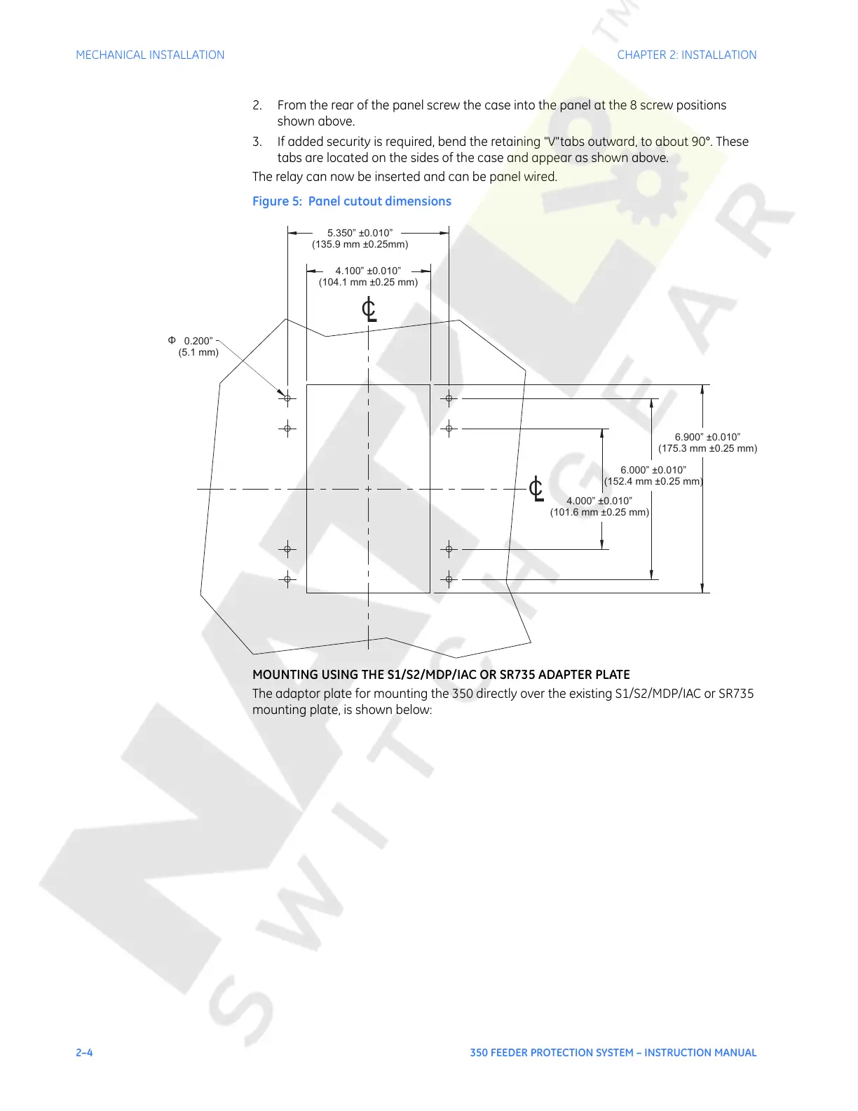
Figure 5: Panel cutout dimensions
MOUNTING USING THE S1/S2/MDP/IAC OR SR735 ADAPTER PLATE
The adaptor plate for mounting the 350 directly over the existing S1/S2/MDP/IAC or SR735
mounting plate, is shown below:
5.350” 0.010”
(135.9 mm 0.25mm)
±
±
4.100” 0.010”
(104.1 mm 0.25 mm)
±
±
0.200”
(5.1 mm)
Φ
6.900” 0.010”
(175.3 mm 0.25 mm)
±
±
6.000” 0.010”
(152.4 mm 0.25 mm)
±
±
4.000” 0.010”
(101.6 mm 0.25 mm)
±
±
C
L
C
L
Courtesy of NationalSwitchgear.com
 Loading...


