2–16 350 FEEDER PROTECTION SYSTEM – INSTRUCTION MANUAL
ELECTRICAL INSTALLATION CHAPTER 2: INSTALLATION
NOTE:
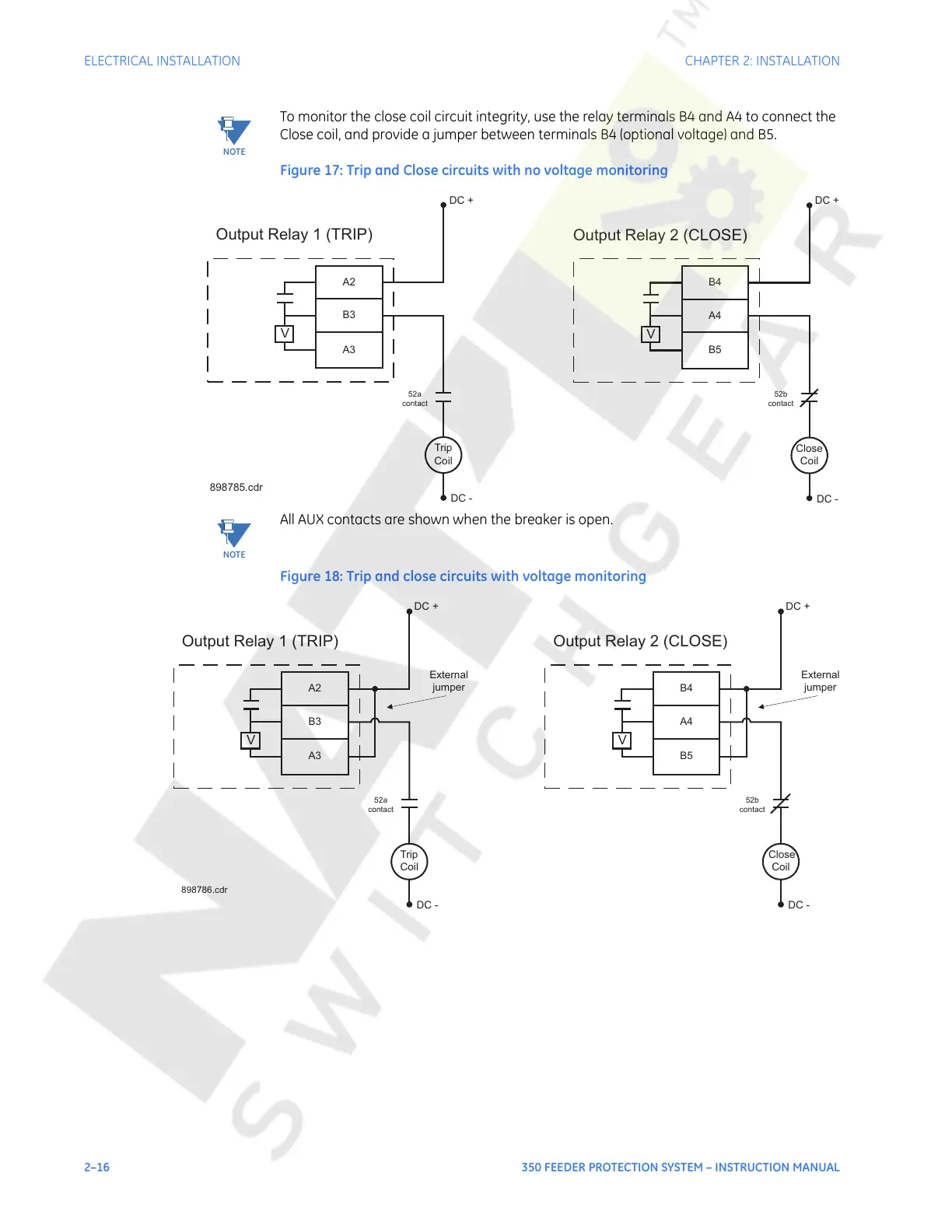
To monitor the close coil circuit integrity, use the relay terminals B4 and A4 to connect the
Close coil, and provide a jumper between terminals B4 (optional voltage) and B5.
Figure 17: Trip and Close circuits with no voltage monitoring
NOTE:
All AUX contacts are shown when the breaker is open.
Figure 18: Trip and close circuits with voltage monitoring
V
A2
B3
A3
Trip
Coil
DC +
DC -
Output Relay 1 (TRIP)
52a
contact
V
B4
A4
B5
Close
Coil
DC +
DC -
Output Relay 2 (CLOSE)
52b
contact
898785.cdr
V
A2
B3
A3
Trip
Coil
DC +
DC -
Output Relay 1 (TRIP)
52a
contact
External
jumper
898786.cdr
V
B4
A4
B5
Close
Coil
DC +
DC -
Output Relay 2 (CLOSE)
52b
contact
External
jumper
Courtesy of NationalSwitchgear.com
 Loading...


