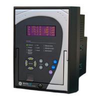
350C FEEDER PROTECTION SYSTEM – INSTRUCTION MANUAL
S4 Controls............................................................................................................................6 - 114
Change setpoint group .........................................................................................................6 - 115
Virtual inputs ..............................................................................................................................6 - 117
Logic elements ..........................................................................................................................6 - 118
Breaker control .........................................................................................................................6 - 124
Cold load pickup.......................................................................................................................6 - 125
Breaker failure........................................................................................................................... 6 - 128
Autorecloser ...............................................................................................................................6 - 130
S5 Inputs/Outputs .............................................................................................................6 - 135
Contact inputs ...........................................................................................................................6 - 135
Output relays .............................................................................................................................6 - 136
Output Relay 1 "Trip" .............................................................................................................6 - 137
Output Relay 2 "Close"..........................................................................................................6 - 139
Auxiliary Output Relays 3 to 6...........................................................................................6 - 141
Critical Failure Relay #7 .......................................................................................................6 - 142
Virtual inputs ..............................................................................................................................6 - 143
Remote inputs ...........................................................................................................................6 - 145
7. MAINTENANCE M1 Relay information.......................................................................................................7 - 3
M3 Breaker maintenance ..............................................................................................7 - 4
Trip coil..........................................................................................................................................7 - 4
Close coil ......................................................................................................................................7 - 6
Breaker trip counter................................................................................................................7 - 9
M4 Breaker monitor..........................................................................................................7 - 12
M5 Relay maintenance ...................................................................................................7 - 13
Ambient temperature ............................................................................................................ 7 - 13
APPENDIX. Change notes ...............................................................................................................Appendix - 1
Manual Revision history................................................................................................ Appendix - 1
Courtesy of NationalSwitchgear.com

 Loading...


