F-20 G650 Generator Protection & Control System GEK-113285A
F.1 FACTORY DEFAULT SETTINGS APPENDIX F
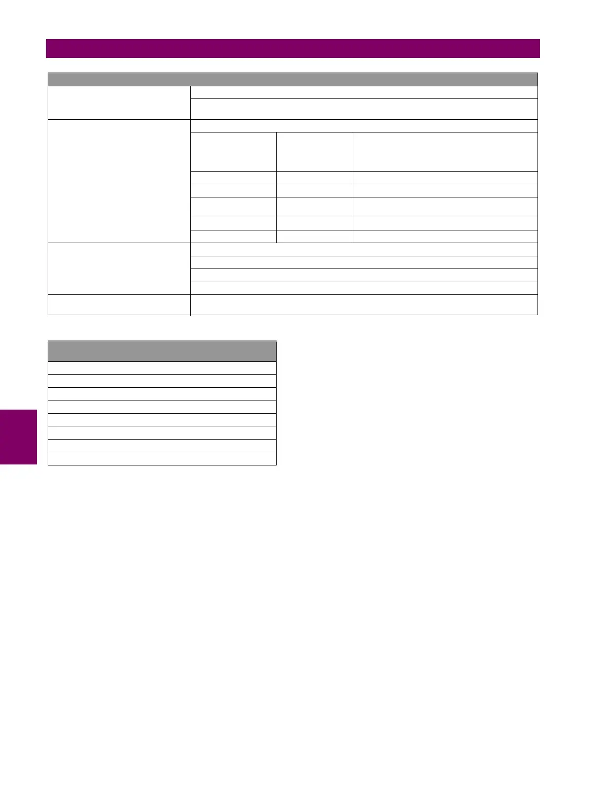
NOTE 2: DESCRIPTION OF X, Y AND Z IN INPUT/OUTPUT BOARDS
X
F, G, H or J, the I/O board name, depending on the Relay model.
F and G are internal Relay boards, and H and J are additional boards available in CIO modules
(remote Bus CAN I/O module)
For the I/O board selection in the relay
model:
I/O BOARD TYPE
ASSOCIATED DIGIT
ENERVISTA 650
SETUP BOARD
SETTINGS
BOARD TYPE
0NONENone
1 16 INP+ 8 OUT Mixed
2
8 INP +8 OUT
+SUPV
Supervision
4 32 INP 32 digital inputs
5 16 INP + 8 ANA 16 digital inputs + 8 analog inputs
CCY
Is the name used for inputs in I/O boards
Mixed, 16 digital inputs: CC1….CC16
Supervision: 8 digital inputs: CC1,..., CC8
32 INP: 32 digital inputs; CC1,...,CC32
0Z
Is the name used for the different outputs in I/O boards, 8 outputs available for any of the two
types of board (01,…., 08)
LIST OF TIME OVERCURRENT CURVES AVAILABLE IN
G650
IEEE extremely/very/moderately inverse
IEC Curve A/B/C/Long-Time Inverse/ Short-Time Inverse
IAC extremely/very/normally/moderately inverse
ANSI extremely/very/normally/moderately inverse
I2t
Definite time
Rectifier curve
User Curve - FlexCurve™ A/B/C/D


 To Next Page