4
NX-6V2 Control
I. GENERAL DESCRIPTION
The NetworX NX-6V2 represents a new approach to security systems design. Drawing on our experience in the world market as the
largest exporter of USA manufactured controls, we have developed the most flexible, durable, and user-friendly control ever seen in
our industry. Featuring sophisticated software, which allows up to 40 users to interface with 16 zones, 2 partitions, and a host of
integrated fire, access, verification, and input/output modules, all reported with the most comprehensive and fast SIA and Contact ID
formats. The NetworX design allows a fully loaded system to be housed in one single metal enclosure, establishing for the first time, a
logical solution and design response to modular systems. Up to 3 modules can be added to expand the capabilities of the NX-6V2. For
product warranty information, please refer to the GE Security Product Catalog.
II. ORDERING INFORMATION
PART # DESCRIPTION PART # DESCRIPTION
NX-6 NX-6V2 Control Only NX-507E Seven Relay Module
NX-6-KIT NX-6V2 Control, NX-108E LED Keypad, 16.5V
40VA Transformer
NX-508E Eight Output Module
NX-108E 8 Zone LED Keypad NX-534E ** Two-Way Listen-In Module
NX-116E 16 Zone LED Keypad NX-540E ** "Operator" Telephone Interface Module
NX-124E 24 Zone LED Keypad NX-591E ** Cellemetry Interface
NX-148E Alphanumeric 48 Zone LCD Keypad NX-1192E 192 Zone LCD Keypad
NX-200 ** Zone Doubling Kit (Includes 100 3.74k and 100
6.98k resistors)
NX-1208E 8 Zone LED Keypad
NX-216E 16 Zone Expander Module NX-1248E 48 Zone LCD Keypad
NX-320E Smart Power Supply and Buss Extender NX-1308E 8 Zone LED Door Design Keypad
NX-408E # 8 Zone Wireless Expansion Module
(UL listed part #60-904)
NX-1316E 16 Zone LED Door Design Keypad
NX-416E # 16 Zone Wireless Expansion Module
(UL listed part #60-904)
NX-1324E 24 Zone LED Door Design Keypad
NX-448E # 48 Zone Wireless Expansion Module
(UL listed part #60-904)
NX-1448E 48 Zone Fixed Language Icon Keypad
** These products have not been tested and approved by Underwriters Laboratories, Inc.
# These wireless devices are only UL listed for residential applications.
III. BOARD INSTALLATION
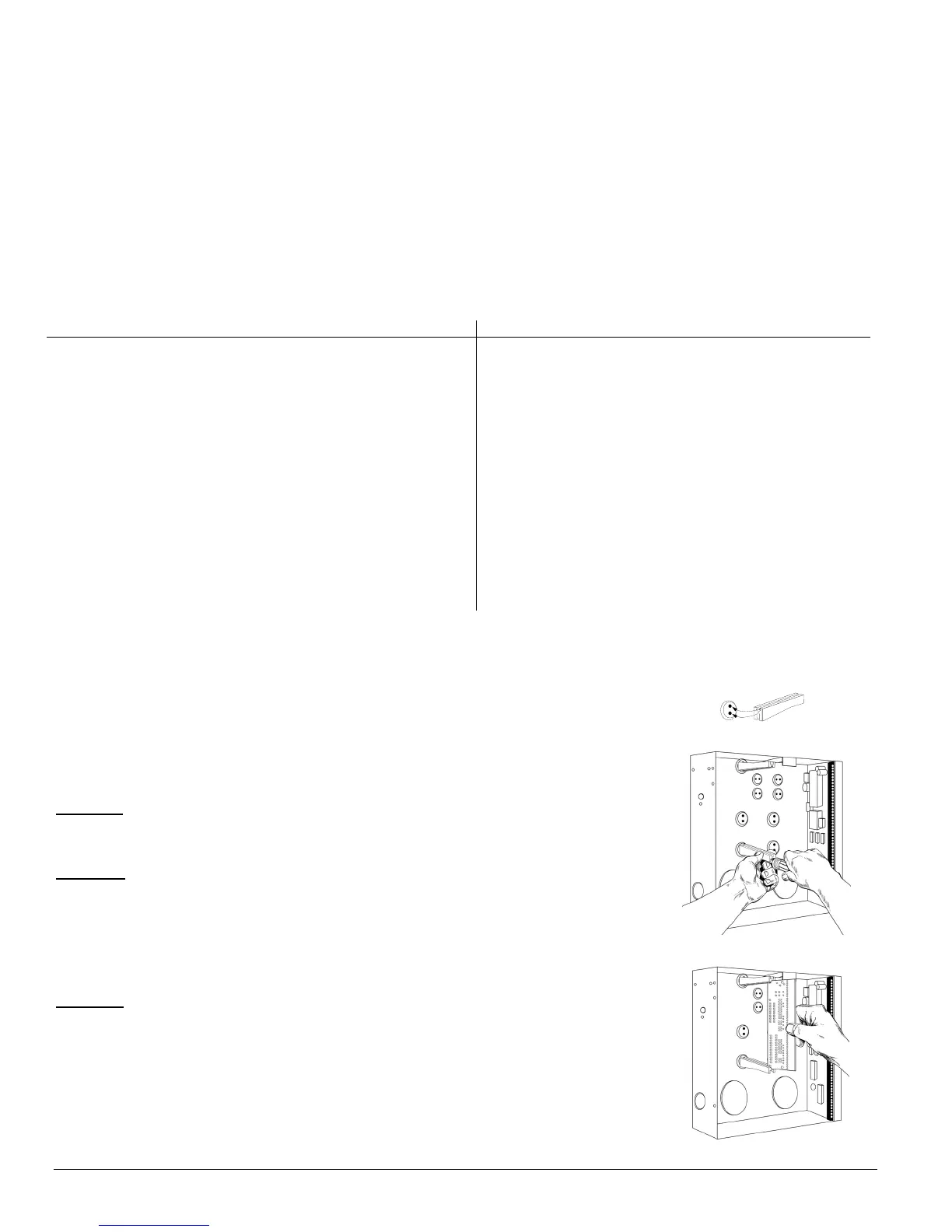
Inside the can, several 2-holed insertion points have been constructed. This allows for either
vertical or horizontal placement of the modules. Notice that each insertion point has two sizes of
holes -a larger hole and a smaller hole.
Diagram 1
: The black plastic PCB guides are grooved on one edge where the PC board will be
seated. The end with the half-moon protrusion fits into the larger hole. The smaller hole is for the
screw.
Diagram 2
: Place the first black plastic PCB guide in the top insertion point, grooved edge
downward. The half-moon protrusion will be in the large hole. It does not require force. Insert
one of the provided screw into the smaller hole (from inside the can) to secure it in place. A
screwdriver should reach through the notch that runs the length of the guide to tighten the screw.
The second PBC guide should be positioned opposite the first (grooved edge up) and placed in
the lower insertion point, using the same procedures described above. Once mounted, screw it
in securely.
Diagram 3: The PC Board should slide freely in the grooves of both guides.

 Loading...


