8
NX-6V2 Control
ASSIGNING AUTHORITY LEVEL:
• Enter [r]-[6]-[master code]. The "Ready" LED will flash.
• Enter the 2 digit user number. The "Ready" LED will illuminate steady and the "Instant" LED will flash.
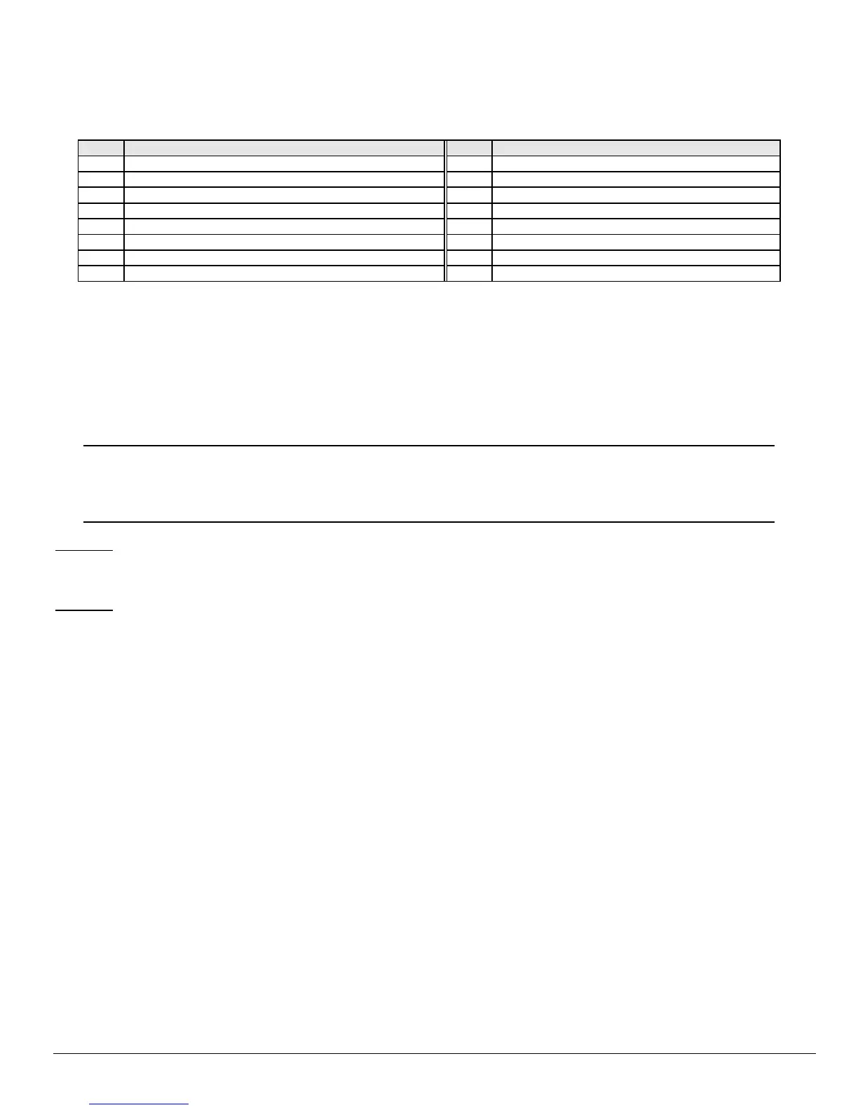
• Refer to the chart below for the description of each LED. Turn the LED on for the features that you desire.
LED ATTRIBUTES IF LED 8 IS OFF LED ATTRIBUTES IF LED 8 IS ON
1 Reserved 1 Activate output #1
2 Arm Only 2 Activate output # 2
3 Arm Only After Close Window 3 Activate output # 3
4 Master arm/disarm (can program other codes) 4 Activate output # 4
5 Arm/disarm code 5 Arm/disarm
6 Allowed to bypass zones (see location 23) 6 Bypass Zones
7 Code will send open / close reports 7 Open / Close Reporting
8 If this LED is on, LEDs 1-7 will use the chart to the right 8 If this LED is off, LEDs 1-7 use the chart to the left
• Enter [r]. The "Instant" LED will illuminate steady.
• Now you are in the partition enable mode. This tells the system what partition this user can arm/disarm. LEDs 1-2 illuminate for
each partition that the user has authorization for. To change any of these numbers, press 1-2 to permit or deny access to the
user. (Example: If LED 2 is lit, then user has assigned access to that partition. By pressing the [2] key, the LED will go off
indicating the user has been denied access to that partition.)
• Enter [r]
• This returns you back to step 2 above, where you may enter another user number to assign attributes for. You may continue this
procedure until you have assigned authority levels to all user numbers - or - you may press [#] key to exit the Assigning Authority
Level Program.
IMPORTANT NOTE
Any master arm/disarm code can add or change a user code if the master code has access to the same partitions as the code
being added/changed. Consequently, when programming the user codes for a partitioned system, leave at least one code (can
be "go to program code" if enabled in location 43) access to all partitions or you will not be able to add new users. If you desire
the end user to be able to add new codes, you must remove the partition authority from all blank codes.
[r]-[9]-[8]
• Pressing [r]-[9]-[8] while the system is disarmed will cause the control to do a callback for a download.
• NOTE: A valid user code may be required after [
r
]-[9]-[8] if enabled in location 41, page 20.
[r]-[9]-[9]
• Pressing [r]-[9]-[9] while the system is disarmed will cause the control panel to seize the phone line for a download.
• NOTE: A valid user code may be required after [
r
]-[9]-[9] if enabled in location 41, page 20.
VII. PROGRAMMING THE CONTROL
ENTERING THE PROGRAM MODE
To enter the Program Mode, press [r]-[8]. At this time, the five function LEDs (Stay, Chime, Exit, Bypass, & Cancel) will begin to flash.
Next, enter the "Go To Program Code" (FACTORY DEFAULT IS [9]-[7]-[1]-[3]). If the "Go To Program Code" is valid, the "Service" LED
will flash and the five function LEDs will illuminate steady. You are now in the Program Mode and ready to select the module to program.
SELECTING THE MODULE TO PROGRAM
Since all modules connected to the NX-6V2 are programmed through the keypad, the module you are programming should be the first
entry. To program the NX-6V2 Control Panel, enter [0]-[#]. The [0] is the module number of the control and [#] is the entry key. Other
module entry numbers can be found in their corresponding manuals.
PROGRAMMING A LOCATION
Once the number of the module to be programmed has been entered, the "Armed" LED will illuminate, indicating it is waiting for a
programming location to be entered. Any location can be accessed by directly entering the desired programming location followed by [#]. If
the location entered is a valid location, the "Armed" LED will extinguish, the "Ready" LED will illuminate and the binary data for the first
segment of this location will be shown by the zone LED's. While entering new data, the "Ready" LED will begin flashing to indicate a data
change in process. The flashing will continue until the new data is stored by pressing [r]. Upon pressing [r], the keypad will advance to
the next segment and display its data. This procedure is repeated until the last segment is reached. Pressing the [#] key will exit from this
location, and the "Armed" LED will illuminate again waiting for a new programming location to be entered. If the desired location is the next
sequential location, press the [POLICE] key. If the previous location is desired press the [FIRE] key. If the same location is desired press

 Loading...


