– 26 –
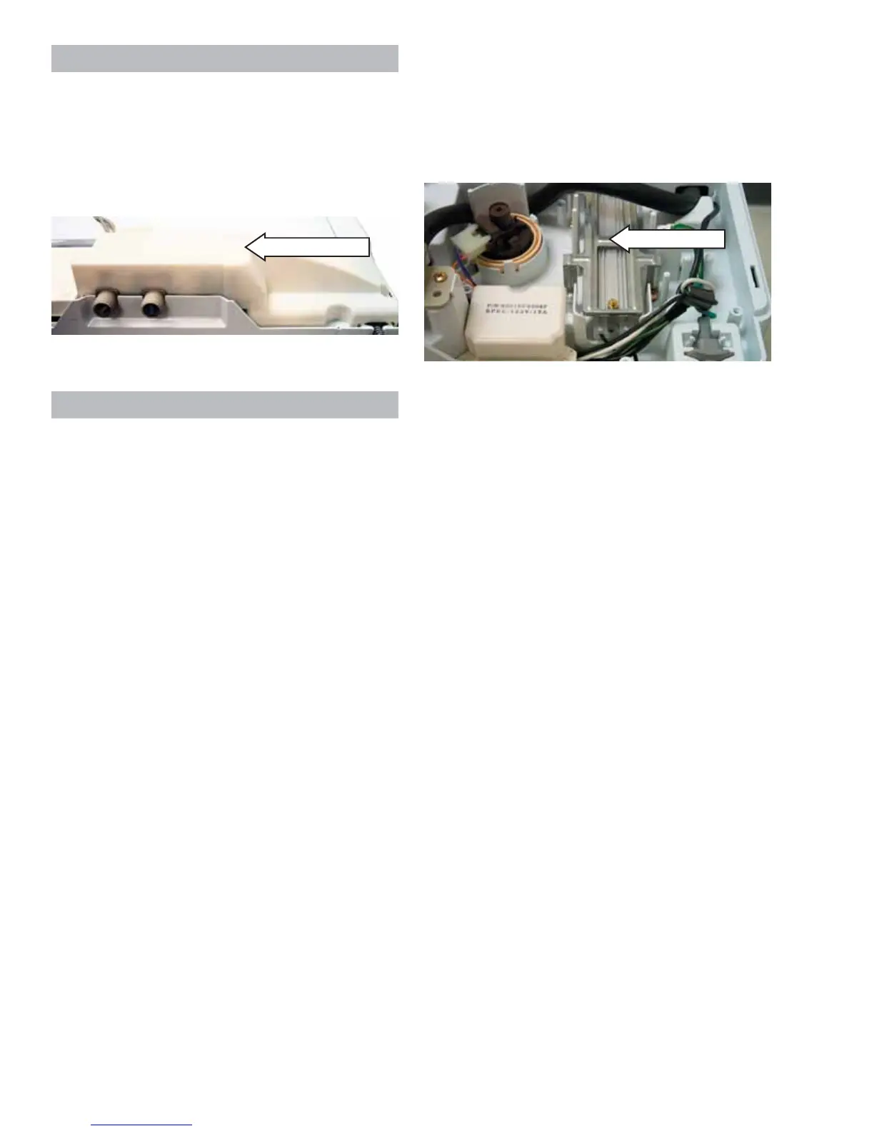
Protective Cover
The protective cover must be removed to access
the following components: water valve assembly,
pressure switch, brake resistor, and RF choke. The
protective cover is held in place by 3 Phillips- head
screws.
Brake Resistor
• The brake resistor absorbs energy from the
reversing of the motor during the brake cycle.
• The brake resistor only operates when the
washer is unplugged or the lid is lifted during a
cycle.
• Under normal operation, the tub coasts to a
stop at the end of a cycle.
• The approximate resistance value of the brake
resistor is 70 Ω.
• If the resistor is shorted, the motor will not start.
• If the resistor opens while the motor is spinning,
the inverter board can be damaged.
• Look for a burnt IC, labeled IC300, on the
inverter board. Both the resistor and inverter
board should be replaced if the IC300 is
damaged. (See Testing the Inverter photo.)
Protective Cover
Brake Resistor
To remove the brake resistor:
1. Remove the 2 Phillips-head screws that hold the
brake resistor in place.
2. Disconnect the wiring to the brake resistor.
 Loading...