– 37 –
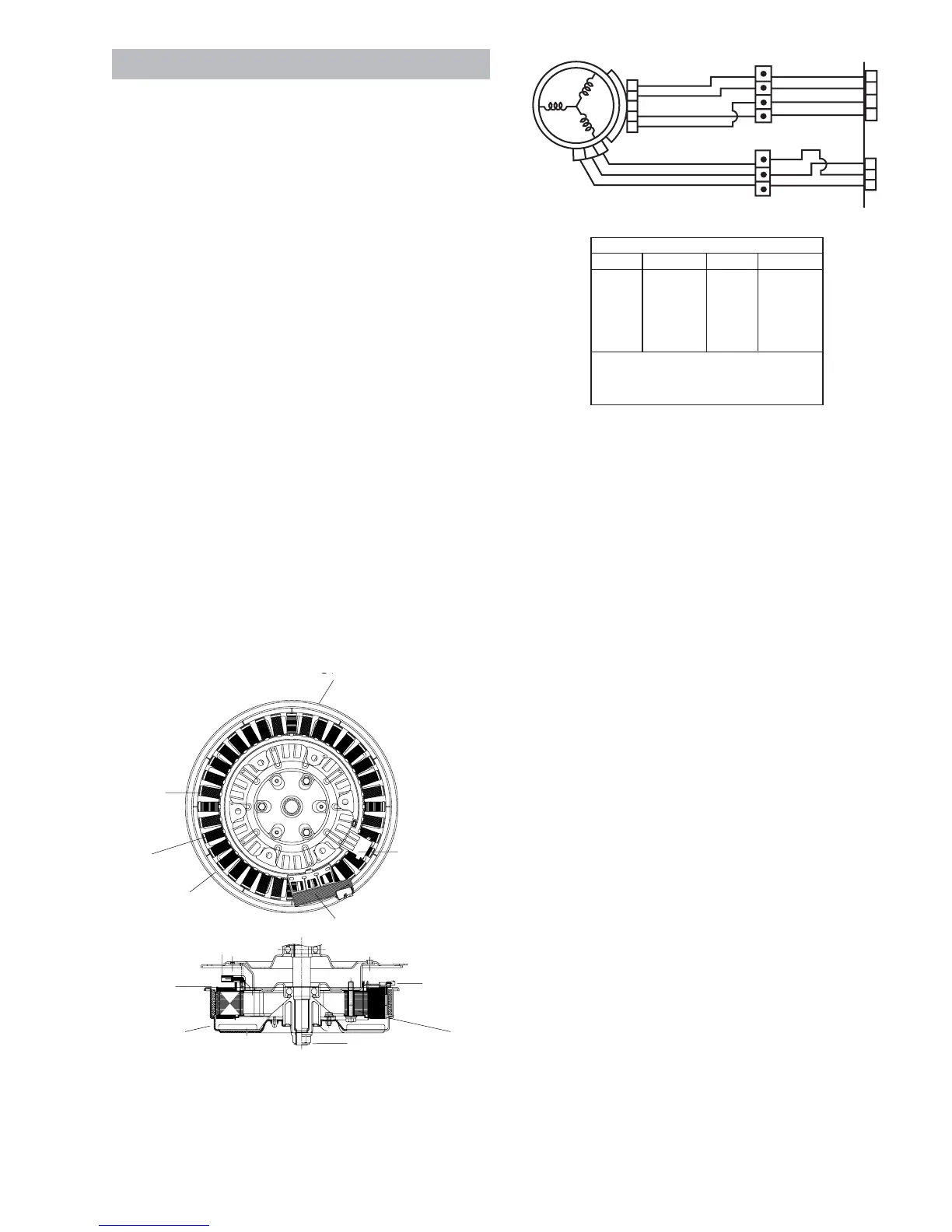
Motor Assembly
• The washer has a direct-drive pulse-width
modulation motor that does not utilize a belt,
transmission, or mechanical brake.
• The motor assembly is composed of a coil-
wound stator, Hall sensor, and permanent-
magnet rotor.
• The motor speed and torque varies when the
pulse width modulated voltage from the inverter
changes frequency.
• The motor turns in the opposite direction when
the inverter reverses electrical polarity to the
motor.
The washer motor has an approximate resistance
value of 8 Ω between any two of the three wires:
• Blue to red - 8 Ω
• Red to yellow - 8 Ω
• Blue to yellow - 8 Ω
Resistance can be measured at the yellow, 3-pin
connector on the inverter board or at the motor. (See
Inverter and Main Board Pin Connectors.)
COIL
STATOR
PERMANENT MAGNET
PERMANENT
MAGNET
HALL SENSOR
POWER
ROTOR
SHAFT
STATOR
ROTOR NUT
RotorROTOR
POWER
HALL SENSOR ASSEMBLY
YX
NX
RX
YX
NX
RX
YX
NX
RX
YX
CX
4
5
2
3
1
2
3
4
12
345
HALL
SENSOR
1
2
3
MOTOR
NX
RX
YX
CX
1
2
3
N
COLOR CODE
LETTERS COLOR
COLOR
LETTERS
AX
BX
CX
NX
OX
PX
RX
SX
GX
VX
WX
YX
LT. BLUE
BLACK
BROWN
DK.BLUE
ORANGE
PINK
RED
GRAY
GREEN
PURPLE
WHITE
YELLOW
THE "X' INDICATES ONE SOLID COLOR-
NO TRACER. WIRES WITH TRACER SHOW
BOTH COLORS, EXAMPLE - WR IS WHITE
WITH RED TRACER.
 Loading...