– 28 –
Water Valve Assembly
The water valve consists of a valve body and 5
solenoid coils. It is only available as a complete
assembly. Each solenoid controls a specifi c water
function.
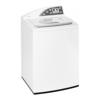
3. Note the placement of the wires, then
disconnect the wiring to the solenoid coils.
• Each coil on the water valve assembly has an
approximate resistance value of 30 Ω.
• The water valves receive power from the
inverter. They are connected to the 6-pin blue
connector on the inverter board. (See Inverter
and Main Board Pin Connectors.)
• When energized, there should be approximately
13 VDC at the appropriate coil.
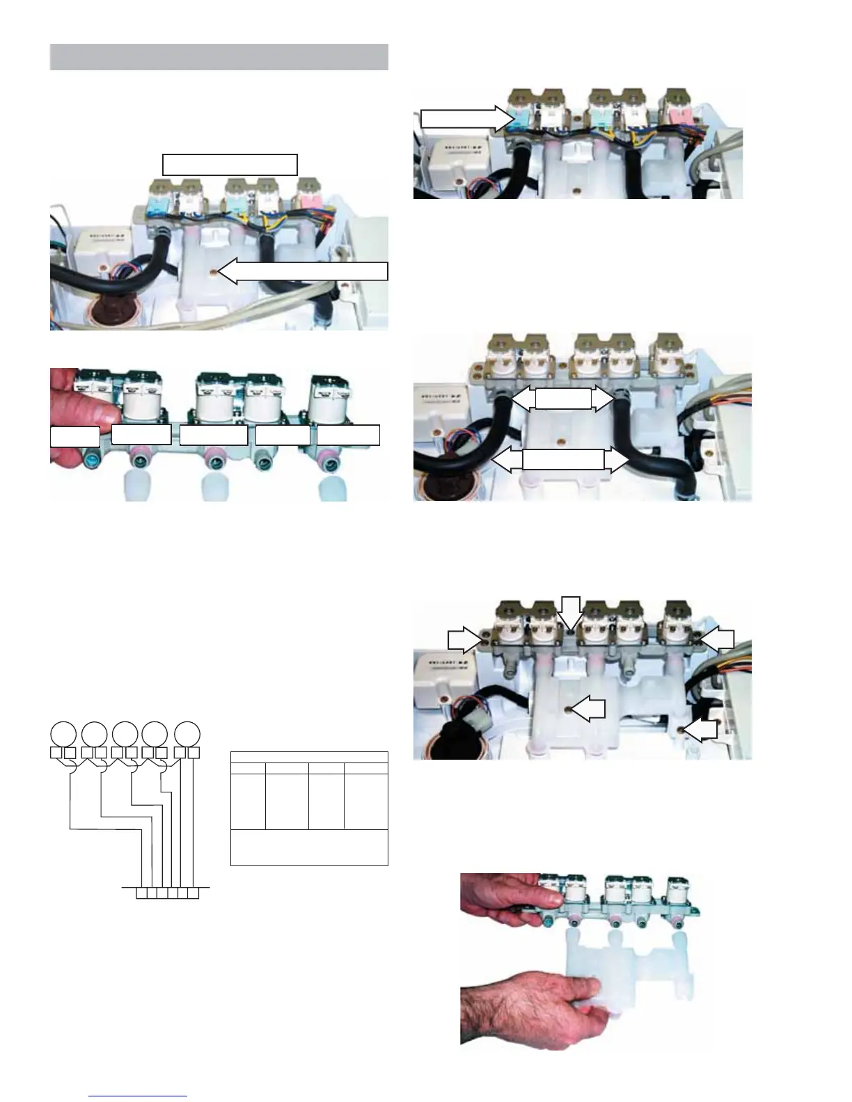
4. Remove the 2 water inlet hoses:
a. Squeeze each clamp and slide it back.
b. Carefully break the hoses loose.
c. Remove the hoses.
5. Remove the 3 Phillips-head screws that hold the
water valve assembly in place and the 2 Phillips-
head screws that hold the water distribution
pipe in place.
BX
NX
AX
WX
AX
WX
PX
16
5
7
2
8
3
9
4
10
YX
NX
OX
BX
CX
YX
NX
SX
NX
165
2
3
4
Inverter
HV
CV
Additive
Bleach
Softener
COLOR CODE
LETTERS COLOR
COLOR
LETTERS
AX
BX
CX
NX
OX
PX
RX
SX
GX
VX
WX
YX
LT. BLUE
BLACK
BROWN
DK.BLUE
ORANGE
PINK
RED
GRAY
GREEN
PURPLE
WHITE
YELLOW
THE "X' INDICATES ONE SOLID COLOR-
NO TRACER. WIRES WITH TRACER SHOW
BOTH COLORS, EXAMPLE - WR IS WHITE
WITH RED TRACER.
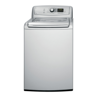
To remove the water valve assembly:
1. Remove the Backsplash.
2. Remove the 3 Phillips-head screws that hold the
protective cover in place.
6. Remove the water valve assembly and
distribution pipe.
Note: The distribution pipe separates from the water
valve assembly as shown below.
Water Distribution Pipe
Water Valve Assembly
Bleach
Softener
Cold Water
Additive Hot Water
Disconnect
Clamps
Inlet Hoses
 Loading...