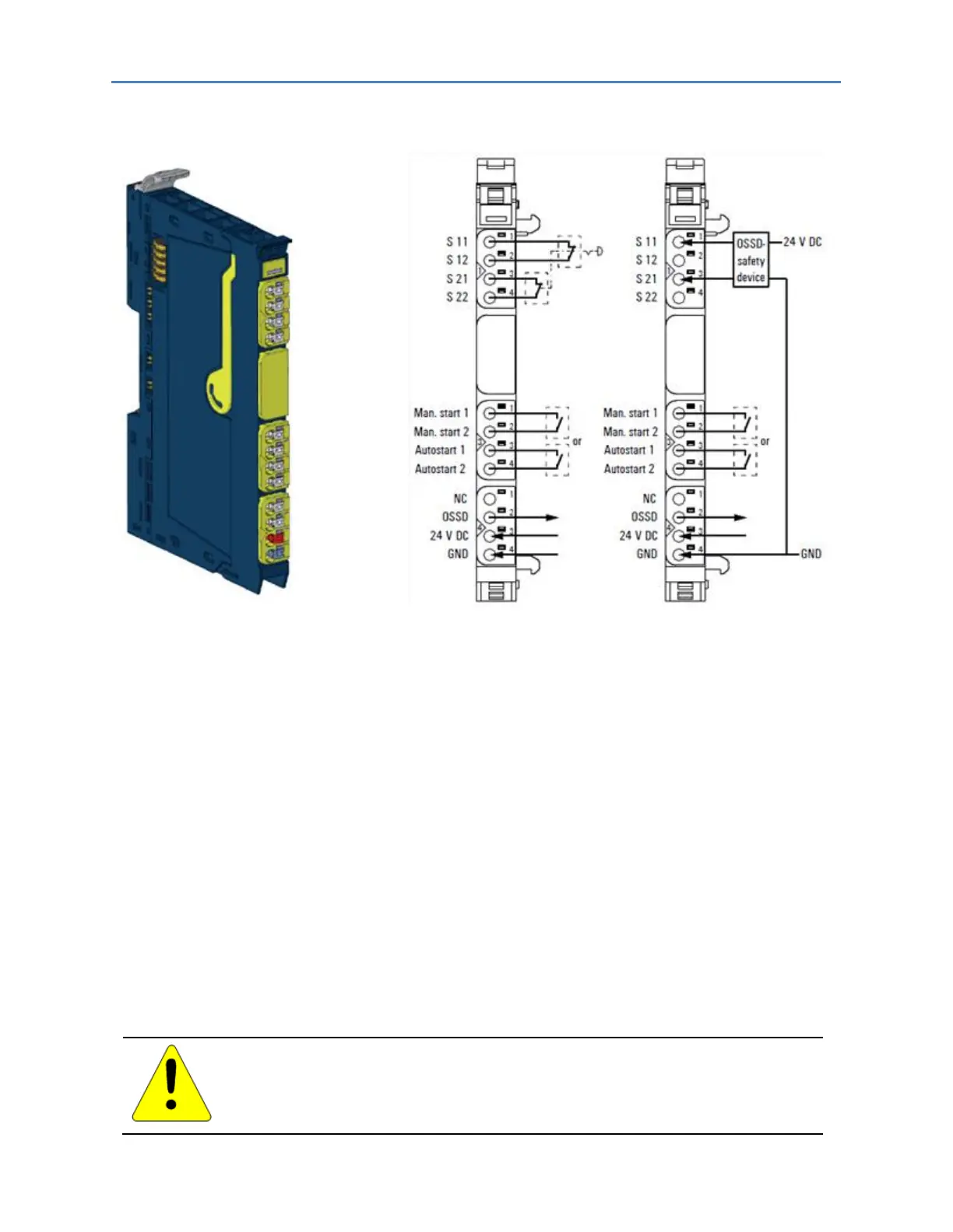
Safe Power-feed Module EP-1901 Connection Diagram EP-1901
The power-feed module EP-1901 enables the safe feed-in for the output current path. The module
ensures that an emergency stop circuit can be monitored, and using the OSSD output it can be
forwarded to a PLC or also cascaded to a further RSTi-EP station. Almost all types of output modules
will be safely switched-off (SIL3/Ple/Cat. 4) when they are placed within the safety segment (refer to
the section, General Contact Information).
For restarting, either the manual or the auto input can be switched. In any case, the system must be
reset by pressing the manual reset within 0.1 to 2 seconds after setting the supply voltage.
The evaluation of test pulses in the safety circuits provides the detection of faults or manipulations of
the wiring. Therefore, every second a low pulse of 1 ms is being generated in each circuit, these
pulses are phase-shifted.
The connections Safety Input 0 (S 11, S 21), Man Start 1 and Autostart 1 are digital inputs Type 3
according to EN 61131-2. The Man Start 1 input can also be controlled by a standard PLC output.
The auxiliary outputs S 12, S 22, Man Start 2 and Autostart 2 must only be used for refeeding the
allocated inputs.
The maximum feed-in current in the output current path is 8 A. The module is sending a pulse (< 1
ms) every 100 ms.
Caution
Risk of material damage - In the case of a maximum power supply of 8 A and
a maximum temperature of +60°C (+140 °F), all wired contacts on the fourth
connector must be connected with 1.5 mm² (15 AWG) wiring.

 Loading...


