14
D
GB
F
E
I
Ru
96446-09.2020-DGbFEIRu
6 | Compressor assembly
Fig. 6
Rigid
fixedpoint
Fig. 7
As short as
possible
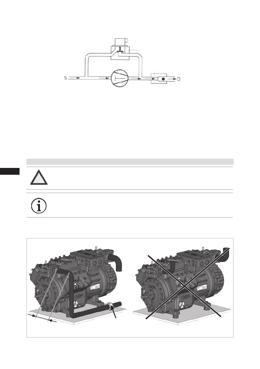
6.6 Layingsuctionandpressurelines
Aruleofthumb: Alwayslaytherstpipesectionstartingfromtheshut-offvalvedownwards
andparalleltothedriveshaft.
ATTENTION Improperlyinstalledpipescancausecracksandtears,theresult
beingalossofrefrigerant.
INFO Proper layout of the suction and discharge lines directly after
the compressor is integral to the system’s smooth running and
vibrationbehaviour.
Important:
- Start unloader may only be employed during the starting phase.
- Check the solenoid valve and the non-return valve regularly for tightness.
- In addition, we recommend to use a heat protection thermostat on the discharge side of the com-
pressor. This protects the compressor against thermal overloading. Connect the heat protection
thermostat in series on the safety chain of the control circuit, to switch off the compressor if
necessary.
- Follow these instructions to avoid thermal overloading.
Solenoid valve dead
Non-return valve open
 Loading...


