D
GB
F
E
I
Ru
31
96446-09.2020-DGbFEIRu
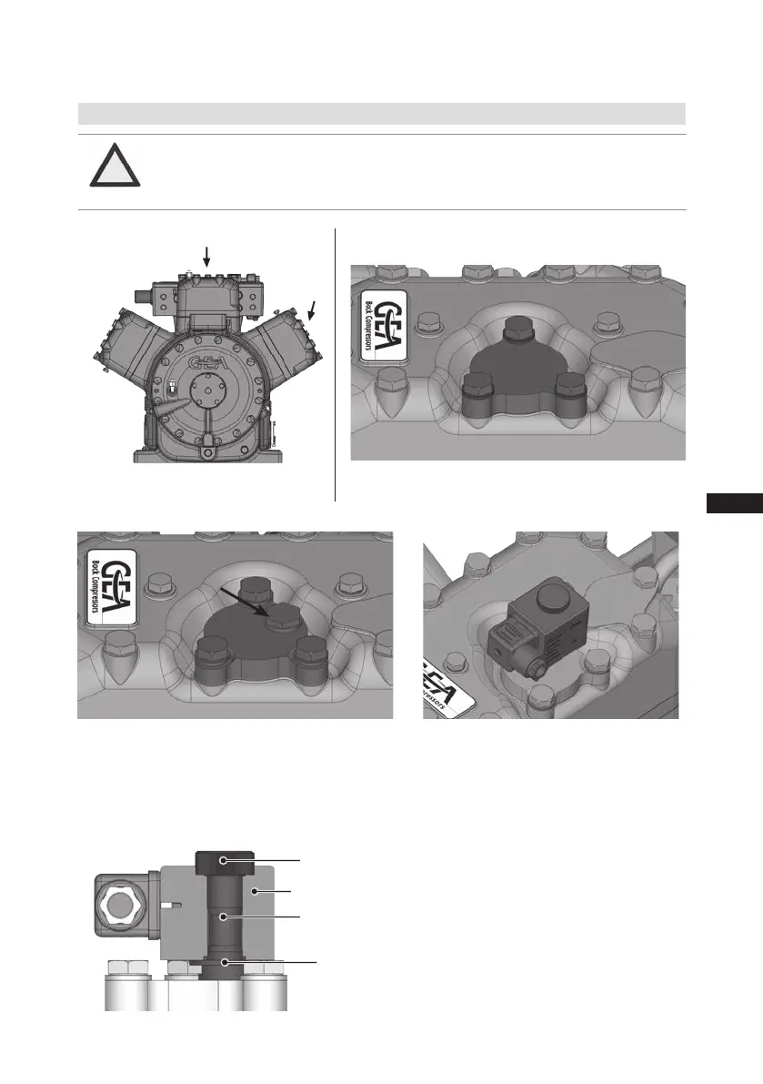
10 | Accessories
10.1Capacityregulator
Delivery condition 1 (from the factory):
Cylinder cover prepared for capacity regulator.
Fig. 18
Fig. 19
LR1
LR2
Fig. 22
Screw in control unit (pilot valve) with seal
ring and tight with 15 Nm.
Wet thread sides with ester oil.
Insert magnetic coil, fasten it with knurled
nut and connect it.
Fig. 21
ATTENTION Ifthe capacity regulator isinstalledatthe factory,thecontrol
component(pilotvalve)issubsequentlyinstalledandconnected
bythecustomer.
Before start-up, remove the cover at the
capacity regulator and replace it with the
enclosed control unit (pilot valve).
Attention!Compressorisunderpressure!
Depressurizethecompressorfirst.
Delivery condition 2 (from the factory):
Capacity regulator installed with cover
(transport protection).
Fig. 20
Cover
Control unit
(pilot valve)
Magnetic coil
Knurled nut
Seal ring
 Loading...


