24
D
GB
F
E
I
Ru
96446-09.2020-DGbFEIRu
7 | Electrical connection
Οnderung
Klebeschilder
0
Datum Name
Datum
Bearb.
Gepr.
Norm
1
04.12.2009
Kelich
22.05.2015
Urspr.
2
Ers. f.
3
Ers. d.
4
Schaltplan
5 6 7
BOCK COMPRESSORS
8
=
+
9
Bl.
MP10 INt69 Bl.
MP10 INt69
INT69 G
Motor Protection MP10
Steuerstrom-
kreis
L
N
Steuerstrom-
kreis
L N
1112 14
B1 B2OG OG
+
-
BT1
Θ
X1 L1 L1 N N 43 43 11 12 14
L S M
X2 1 2 3 4 5 6
R1
R2
+
-
BT1
Θ
+
-
BT2
Θ
Terminal box
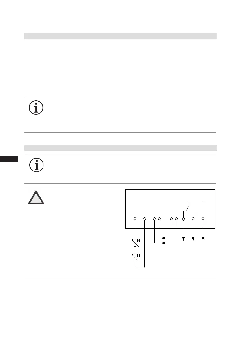
Fig. 14
6
ATTENTION
Measure circuit BT1 and BT2
(PTCsensor)mustnotcome
into contact with external
voltage.
Thiswoulddestroythetrigger
unitINT69GandPTCsensors.
7.6 ElectronictriggerunitINT69G
7.7 ConnectionofthetriggerunitINT69G
The compressormotor is tted with cold conductortemperature sensors(PTC) connectedto the
electronic trigger unit INT69 G in the terminal box. In case of excess temperature in the motor
winding, the INT69 G deactivates the motor contactor. Once cooled, it can be restarted only if the
electronic lock of the output relay (terminals B1+B2) is released by interrupting the supply voltage.
The hot gas side of the compressor can also be protected against overtemperature using thermal
protection thermostats (accessory).
The
unittripswhenanoverloadorinadmissibleoperatingconditionsoccur.Findandremedy
the cause.
INFO Therelayswitchingoutputisexecutedas aoatingchangeover
contact.Thiselectricalcircuitoperatesaccordingtothequiescent
currentprinciple,i.e.therelaydropsinto atheidlepositionand
deactivatesthemotorcontactorevenincaseofasensorbreakor
open circuit.
INFO ConnectthetriggerunitINT69Ginaccordancewiththecircuitdia-
gram.Protectthetriggerunitwithadelayed-actionfuse(FC2)of
max.4A.Inordertoguaranteetheprotectionfunction,installthe
triggerunitastherstelementinthecontrolpowercircuit.
Control circuit
 Loading...


