D
GB
F
E
I
Ru
25
96446-09.2020-DGbFEIRu
7 | Electrical connection
7.8 FunctiontestofthetriggerunitINT69G
Before commissioning, after troubleshooting or making changes to the control power circuit, check
the functionality of the trigger unit. Perform this check using a continuity tester or gauge.
Gaugestate Relayposition
Deactivated state 11-12
INT69 G switch-on 11-14
Remove PTC connector 11-12
Insert PTC connector 11-12
Reset after mains on 11-14
Relay position INT69 G
B2 12 14 11
Fig. 15
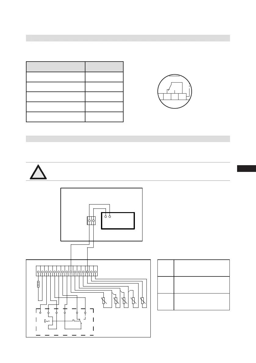
7.9 ElectronictriggerunitINT69GatHCandLGcompressors
The supplied INT69 G must be connected according to the wiring diagram shown here in a separate
control cabinet, which must be installed outside each danger zone.
BT1 Cold conductor (PTC
sensor) motor winding
BT2 Heat protection thermo-
stat (PTC sensor)
EB1 Oil sump heater
ATTENTION Installheatprotectionthermostatsandcoldconductormotor
windinginseries!
Οnderung
2
0
Datum Name
Datum
Bearb.
Gepr.
Norm
1
04.12.2009
bauknecht
08.05.2020
Urspr.
2
Ers. f.
3
Ers. d.
4
HG44e/56e HC
5 6 7
BOCK COMPRESSORS
8
=
+
9
Bl.
5 Bl.
4
3
DELTA- P II
Schaltschrank
EB1
BT2
BT2
BT1
vio bn bu gr og pk
1 2 3 4 5 6 7 8 10 11 12
INT69G
Οnderung
2
0
Datum Name
Datum
Bearb.
Gepr.
Norm
1
04.12.2009
bauknecht
08.05.2020
Urspr.
2
Ers. f.
3
Ers. d.
4
HG44e/56e HC
5 6 7
BOCK COMPRESSORS
8
=
+
9
Bl.
5 Bl.
4
3
DELTA- P II
EB1
BT2
BT2
BT1
vio bn bu gr og pk
1 2 3 4 5 6 7 8 10 11 12
BT2
13 20 21
09
Öl-Temp.
Switch cabinet
Fig. 16
 Loading...


