Do you have a question about the GEA ECOVENT and is the answer not in the manual?
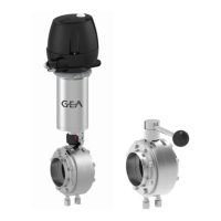
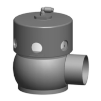
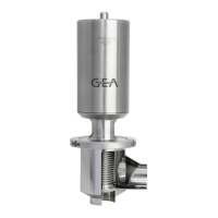
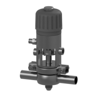
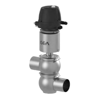
The GEA ECOVENT® Valve Type W_/ECO is a hygienic valve designed for converging streams of liquid within a pipe section. It is available in various sizes, from DN 25 to DN 100 (1" to 4" OD), and is constructed from stainless steel 1.4404 (AISI316L) / 1.4571 for product contact parts. The valve can be installed in any position, provided the valve housing and pipe system can drain properly. For horizontal installations, the vent hole in the actuator should be horizontally aligned, and the actuator may require support to mitigate stress on valve stem seals and prevent leakage.
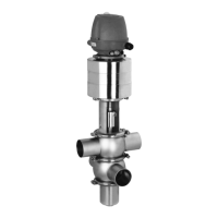
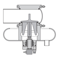
The valve's functional description details two actuator types: spring-to-close (NC) and spring-to-open (NO). For the spring-to-close (NC) actuator, the valve is closed in its idle position. Identification features include the valve disk shoulder being at the bottom in the lantern (Z.2) and the air connection/locking screw being located below (Z.1). When equipped with a T.VIS control top, a permanent green light (1) indicates the valve is closed (idle position), while a permanent yellow light (1) signifies the valve is open (actuator activated). For the spring-to-open (NO) actuator, the valve is open in its non-actuated position. Identification features include the valve disk shoulder being at the top in the lantern (A.2) and the air connection/locking screw being located at the top (A.1). With a T.VIS control top, a permanent green light (1) indicates the valve is open (idle position), and a permanent yellow light (1) indicates the valve is closed (actuator activated). The actuator closing direction can be modified, but it is crucial to check the actuator size as actuation forces may be insufficient after reversal. Proximity switches and feedback buttons must be reset after such modifications.
Key technical specifications include:
Usage features: The valve is intended for use in converging liquid streams within a pipe. It is crucial to ensure the medium flows in the opening direction of the valve disk to prevent pipe hammers. Hydraulic pressure build-up in closed pipe systems during valve switching can damage seals. The valve is classified under the Pressure Equipment Directive 2014/68/EU, category 1, for nominal diameters ≥ IPS 4" (DN 125) for fluid group II. Smaller nominal diameters fall under Article 4, Paragraph 3, requiring sound engineering practice. For explosive atmospheres, ATEX-certified valves and compliance with Directive 2014/34/EC are mandatory.
Maintenance features: Maintenance includes regular inspections of seals, pneumatic connections, electrical connections, and safety signs. Servicing intervals vary based on operating conditions, such as daily use, switching frequency, and product/cleaning agent temperature. For media at 60 °C to 130 °C, servicing is recommended every 3 months; for media < 60 °C, every 12 months. When removing the valve, all pipe system elements must be drained, power supply disconnected, and the valve removed from the pipe section. Special attention is required for spring-closing valves (NC) to release spring tension by pressurizing the actuator before detaching clamp connections to prevent injury. Sensitive sealing surfaces in the actuator must be protected from dirt and impact. Assembly involves careful installation of valve inserts, ensuring correct orientation and tightening torques for components like the valve disk, lantern, mounting base, and switch bar. Lubrication of threads and seals is critical, using recommended lubricants like Rivolta F.L.G. MD-2 and PARALIQ GTE 703, which are food-grade approved and beer froth resistant. V-rings should be replaced without grease, using water with a drop of washing-up liquid for easier fitting. Troubleshooting covers issues like the valve not working (controller fault, no/low compressed air, electrical fault, defective solenoid valve), valve not closing (dirt/foreign material), valve closing slowly (dry O-rings), and leakage (defective O-rings, seal ring, or V-rings). Decommissioning involves switching off compressed air and the main switch, securing against reactivation, and observing storage conditions for longer shutdowns. Disposal requires separating materials (metals, synthetics, electronic parts, lubricants) and adhering to statutory waste disposal regulations. Actuators with pre-stressed springs must never be opened and should be returned to GEA Tuchenhagen for proper disposal.
| Brand | GEA |
|---|---|
| Model | ECOVENT |
| Category | Control Unit |
| Language | English |