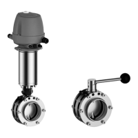
Hint!
Welding method: We recommend using the automatic orbital welding
method. All welding work should only be performed by certified
welders or machine operators (orbital welders).
Housing O-rings: When assembling the valve always replace the
housing O-rings to ensure that the valve is tight.
6.5 Pneumatic connections
6.5.1 Air Requirement
Actuator type
Actuator Ø
[mm]
Air requirement
(dm
3
n
/Stroke)
dm
3
n
at 1.01325
bar
at 0 °C as per
DIN 1343
Use
A... 98 0.16
DN 25 - DN 100
1" - 4" OD
2" - 4" IPS
B... 109 0.26
C... 135 0.42
D... 170 0.70
E... 210 1.10
R...¹ 170 1.60
S...¹ 210 2.00
T...¹ 210 2.20
D...6 170 1.30
DN 125 + DN 150
6" OD, 6" IPS
E...6 210 2.00
S...6 261 3.20
T...6¹ 210 4.00
U...6¹ 261 5.20
1
Actuators with booster cylinder for increasing the pneumatic actuating force
when lower control air pressures are used
6.5.2 Establishing Hose Connections
To ensure reliable operation, the compressed air hoses must be cut exactly at a
right angle.
Tools required:
•
A hose cutter
Carry out the following steps:
Assembly and installation
Pneumatic connections
430BAL008331EN_4
30 18.02.2022
 Loading...