80209C_MHW_850-1650-1850_20-2020_ENG_pag. 25
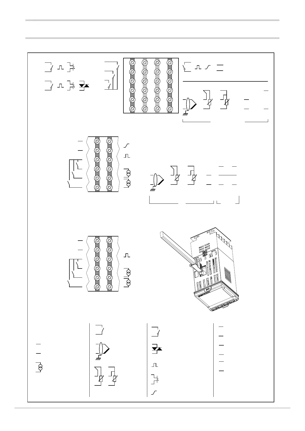
2.3. 850 connection diagrams
2.3.1. General diagram
6
5
4
3
2
1
7
8
9
10
11
12
19
20
21
22
23
24
18
17
16
15
14
13
18
17
16
15
14
13
7
8
9
10
11
12
T
T
NO
C
+
-
~
~
+
-
+
-
+
-
~
PWR
~
B (Data +)
A (Data -)
+
-
VT
+
-
VP
~
PWR
~
+
-
+
-
+
-
~
~
+
-
+
-
+
-
+
-
TT
+
-
+
B (Data +)
A (Data -)
NO
C
NO
C
NO
B (Data+)
A (Data-)
C
OUT 1
OUT 2
A
G
A1
CT1
CT2
OUT 2
IN 1
IN 2
IN 3
COM
OUT 3
OUT 4
COM
OUT 3
+
-
VT1
60 mV, 1 V, 20 mA
1 V, 5 V, 10 V, 20 mA
+
-
TT
+ +
-
+
-
VP
60mV
+
-
VT2
5 V, 10 V
(AL1)
(AL2)
OUT 4
(AL3 / HB)
= 1 = 2 o 3
18
17
16
15
14
13
7
8
9
10
11
12
+
B (Data +)
RS485 Bridge
A (Data -)
CT1
CT2
IN 1
IN 2
IN 3
COM
OUT 4
(AL3 / HB)
Without Ethernet communication option
LEGEND
Power supply
Linear input
voltage / current
Supply transmitter
Supply potentiometer
Input for
current transformer
Relay output
Long-life solid state
relay output
Isolated analog output
Isolated digital
inputs
RS485 serial line
Logic output
Isolated logic output
Thermocouple
input
Input
PT100
JPT100
2 / 3 wires
Auxiliary input
CT1 = current transformer
CT2 = second current transformer for 2-phase /3-phase load
for models with the auxiliary input option
With Ethernet communication option
CT1 = current transformer
CT2 = second current transformer for 2-phase /3-phase load
Main input