80209C_MHW_850-1650-1850_20-2020_ENG_pag. 40
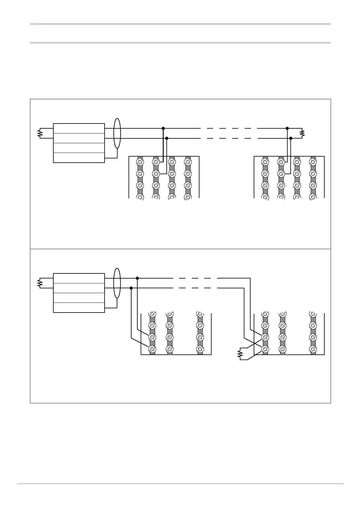
2.6. Serial RS485 Wiring Diagram
Up to 31 controllers may be connected in parallel on phy-
sical line RS485, independently of which option is selected
(Master Modbus (G), rete bridge RS485 (ME), Modbus RTU
Slave (M0) ); they may even be of different models.
The line must be terminated with a resistor (120 Ω, 1/2 W) at
each end.
Output 1 type G options have an integrated 120 Ohm termi-
nation, while options M0 and ME require addition of termina-
tion outside the instrument.
6
5
4
3
7
8
9
10
18
17
16
15
19
20
21
22
6
5
4
3
7
8
9
10
18
17
16
15
19
20
21
22
RS485
Shield
120 Ω
1/2 W
Ω
+ -
B (+)
A (-)
Frame ground (FG)
+
-
850
850
Figure 13 - RS485 connection for 850 controller with optional communication (M) = M0
4
3
2
1
45
46
47
48
28
27
26
25
4
3
2
1
45
46
47
48
28
27
26
25
RS485
Shield
120 Ω
1/2 W
Ω
+
-
Frame ground (FG)
+
-
1650 - 1850
1650 - 1850
B (+)
A (-)
Figure 14 - RS485 connection for 1650 and 1850 controllers with optional communication (M) = M0
Configurazione linearizzazione
custom