ADL300 - Fast installations and commissioning Pag. 13 of 52
4.2 Power section wiring
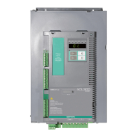
4.2.1 Connection of shielding (recommended)
Loosen the two screws (B), put the metal support (A) (optional, POWER SHIELD KIT) in place and screw down tightly.
Fasten the power cable shield to the omega sections (C) as illustrated in the figure.
• Sizes 4 and 5 : for these sizes the metal support (A) is not provided. Cable shielding must be provided by the installer.
4.2.2 EMC guide line
In a domestic environment, this product may cause radio inference, in which case supplementary mitigation
measures may be required.
The converters are protected in order to be used in industrial environments where, for immunity
purposes, large amounts of electromagnetic interference can occur. Proper installation practices
will ensure safe and trouble-free operation. If you encounter problems, follow the guidelines which
follow.
- Check for all equipment in the cabinet are well grounded using short, thick grounding cable connected to a
common star point or busbar. Better solution is to use a conductive mounting plane and use that as EMC
ground reference plane.
- Flat conductors, for EMC grounding, are better than other type because they have lower impedance at
higher frequencies.
- Make sure that any control equipment (such as a PLC) connected to the inverter is connected to the same
EMC ground or star point as the inverter via a short thick link.
- Connect the return ground from the motors controlled by the drives directly to the ground connection ( )
on the associated inverter.
- Separate the control cables from the power cables as much as possible, using separate trunking, if
necessary at 90º to each other.
- Whenever possible, use screened leads for the connections to the control circuitry
- Ensure that the contactors in the cubicle are suppressed, either with R-C suppressors for AC contactors or
‘flywheel’ diodes for DC contactors fitted to the coils. Varistor suppressors are also effective. This is
important when the contactors are controlled from the inverter relay.
- Use screened or armored cables for the motor connections and ground the screen at both ends using the
cable clamps.
For further information regarding electro-magnetic compatibility standards, according to Directive EMC 2014/30/EU, conformity checks carried
out on Gefran appliances, connection of filters and mains inductors, shielding of cables, ground connections, etc., consult the “Electro-magnetic
compatibility guide” (https://www.gefran.com/en/download/2700/attachment/all).
A
B
C
O
pt
io
n
al
Po
w
er
Shield kit:
- Cod. S726101 (s
iz
e
s 1
a
nd
2)
-
Co
d.
S
72
65
0
1 (size 3)