4-19
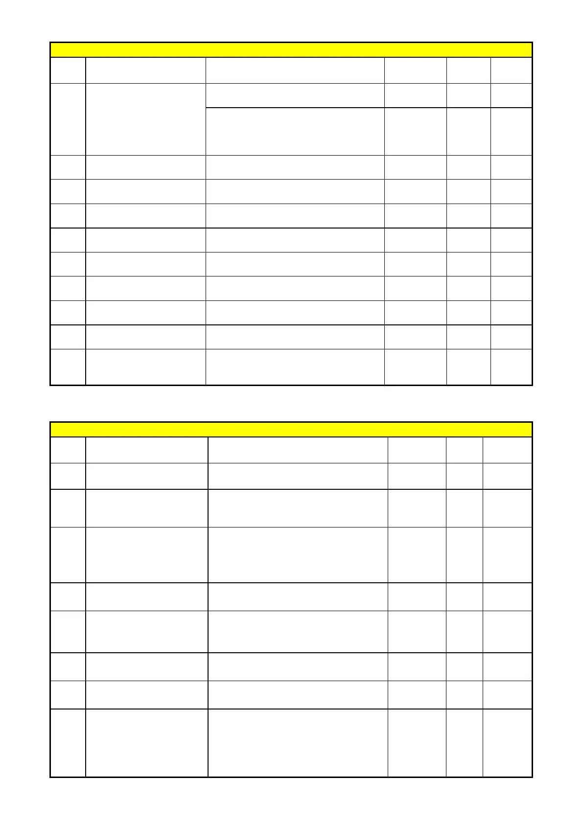
Group 08- Drive & Motor Protection functions
No. Description Range
Factory
Unit Note
2: Coast to stop
3: Continue running, when warning
level is reached.
Coast to stop, when protection
08-11
PTC Signal Smoothing
Time
0.01~10.00 0.2 s
08-12
1~300 60 s
08-13
PTC Protection Level 0.1~10.0 0.7 V
08-14
PTC Detection Level
Reset
0.1~10.0 0.3 V
08-15
PTC Warning Level 0.1~10.0 0.5 V
08-16
Fan Control Temperature
Level
10.0~50.0 50.0
°C
Over current protection
level
Over current protection
time
08-19
Motor Overload
Protection Level
0: Motor Overload Protection Level 0
1: Motor Overload Protection Level 1
2: Motor Overload Protection Level 2
0
Group 09- Communication function setup
No. Description Range
Factory
Unit Note
09-00
Assigned Communication
1 ~ 32 1 - *2*3
09-01
Communication Mode
Select
1:Modbus ASCII code
0 - *2*3
09-02
Baud Rate Setting
(bps)
0:4800
1:9600
2:19200
2 bps *2*3
09-03
Stop Bit Selection
0:1 Stop Bit
0 - *2*3
09-04
Parity Selection
0:Without Parity
1:With Even Parity
0 - *2*3
09-05
Data Format
0: 8-Bits Data
0 - *2*3
09-06
Communication time-out
0.0 ~ 25.5
0.0 s
09-07
Communication time-out
operation selection
0: Deceleration to stop (set by 00-15:
Deceleration time 1)
1: Coast to stop
2: Deceleration to stop (set by 00-17:
Deceleration time 2)
0 -

 Loading...


