4-43
Output relay RY1. function descriptions:
1) 03-11 =
0
. RY1 will be ON with Run signal.
2) 03-11 =
1
. RY1 will be ON with inverter Faults.
3) 03-11 =
2
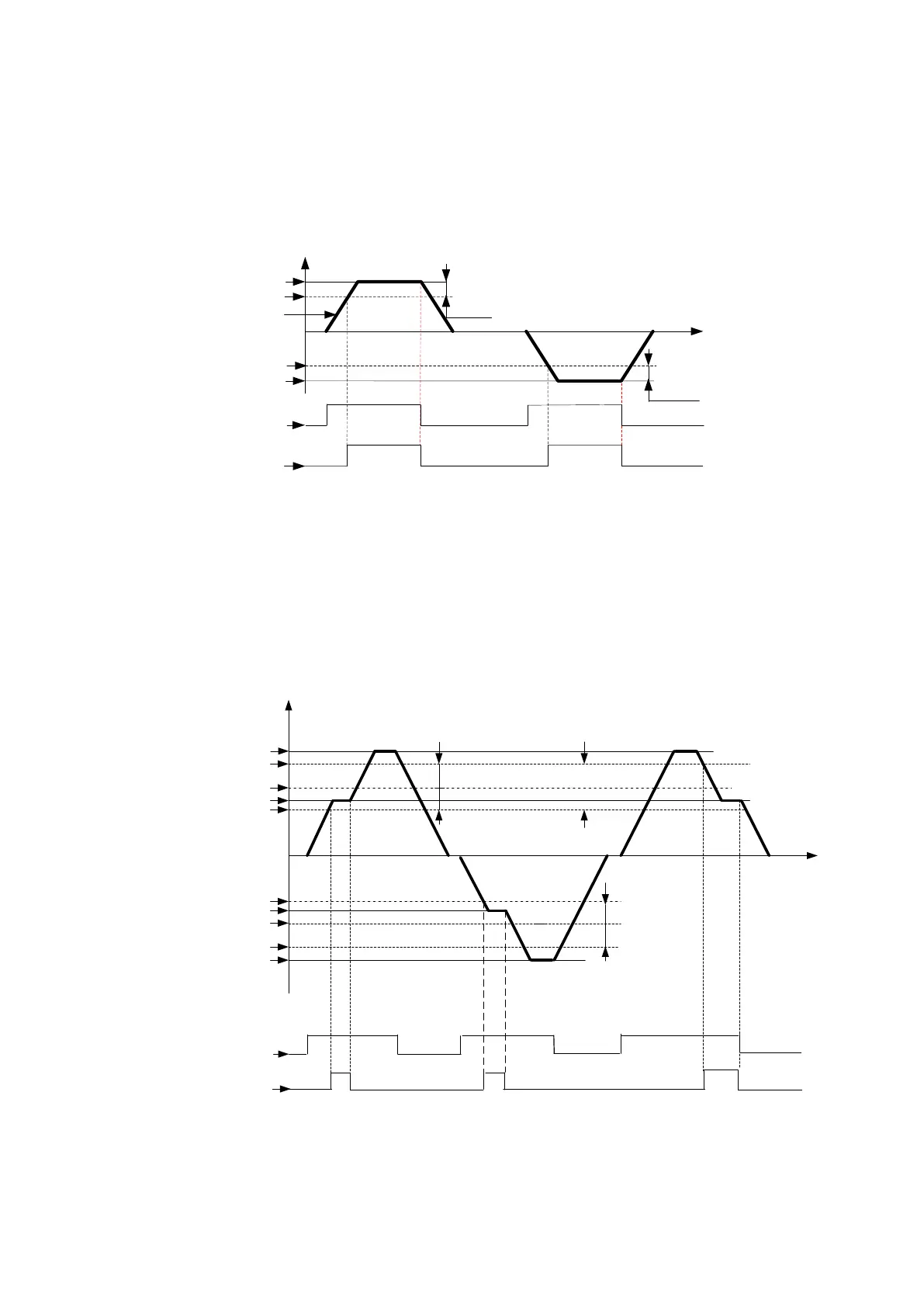
. RY1 will be ON when Output Frequency reached Setting Frequency.
FWD
REV
Setting Freq.
(03-14)
When Output Freq. = Setting Frequency – Frequency Detection Width (03-14),
Relay Output will be ON.
Output Freq.
ON ON
Relay Output
Hz
Time
0
RUN RUN
Run Command
Setting Freq. – (03-14)
(03-14)
Setting Freq. + (03-14)
Setting Freq.
Example:Setting Freq. =30, and Frequency Detection Width (03-14) =5,
Relay will be ON when output frequency reached 25Hz to 30Hz and Run Command
is on (Allowable tolerance ±0.01).
4) 03-11=
3
RY1 will be ON when Setting Freq. and Output Frequency reached (03-13 +/- 03-
14).
FWD
REV
Setting Freq
. 2
Setting Freq. 1
Setting Freq. 1
Setting Freq. 2
2* (03-14)
Relay Output
ON
ON
ON
RUN
RUN
RUN
RUN Command
FWD
Hz
Time
0
When Frequency Detection Range Lower Limit<Setting Freq.<Frequency Detection Range Upper Limit
And, Frequency Detection Range Lower Limit<Output Freq.<Frequency Detection Range Upper Limit,
Relay output will be ON, Allowable tolerance ±0.01,
(03
-13)
(03-13)+(03-14)
(03-13)-(03-14)
(03-13)
(
03-13)-(03-14)
(03-13)+(03-14)
2* (03-14)
Frequency Detection Range Upper Limit
Frequency Detection
Range
Lower Limit
Example:
Frequency Detection Level (03-13) =30, and Frequency Detection Width (03-14) =5 cause
Frequency Detection Range upper limit = 35, and Frequency Detection Range lower limit
= 25. So RY1 will be on when Setting Freq. and Output Freq. are both under these limits;
on the other hand, RY1 will be off when Setting Freq. and Output Freq. are not under
these limits either.

 Loading...


