Cinterion
®
ALAS5 Hardware Interface Overview
2 Interface Characteristics
32
ALAS5_HIO_v00.030a 2019-04-01
Confidential / Preliminary
Page 16 of 50
2 Interface Characteristics
ALAS5 is equipped with an SMT application interface that connects to the external application.
The SMT application interface incorporates the various application interfaces as well as the RF
antenna interface.
2.1 Application Interface
2.1.1 USB Interface
ALAS5 supports a USB 3.0 Super Speed (5Gbps) device interface, and alternatively a USB 2.0
device interface that is High Speed compatible. The USB interface is primarily intended for use
as command and data interface, and for downloading firmware.
The USB host is responsible for supplying the VUSB_IN line. This line is for voltage detection
only. The USB part (driver and transceiver) is supplied by means of BATT+. This is because
ALAS5 is designed as a self-powered device compliant with the “Universal Serial Bus Specifi-
cation Revision 3.0”
1
.
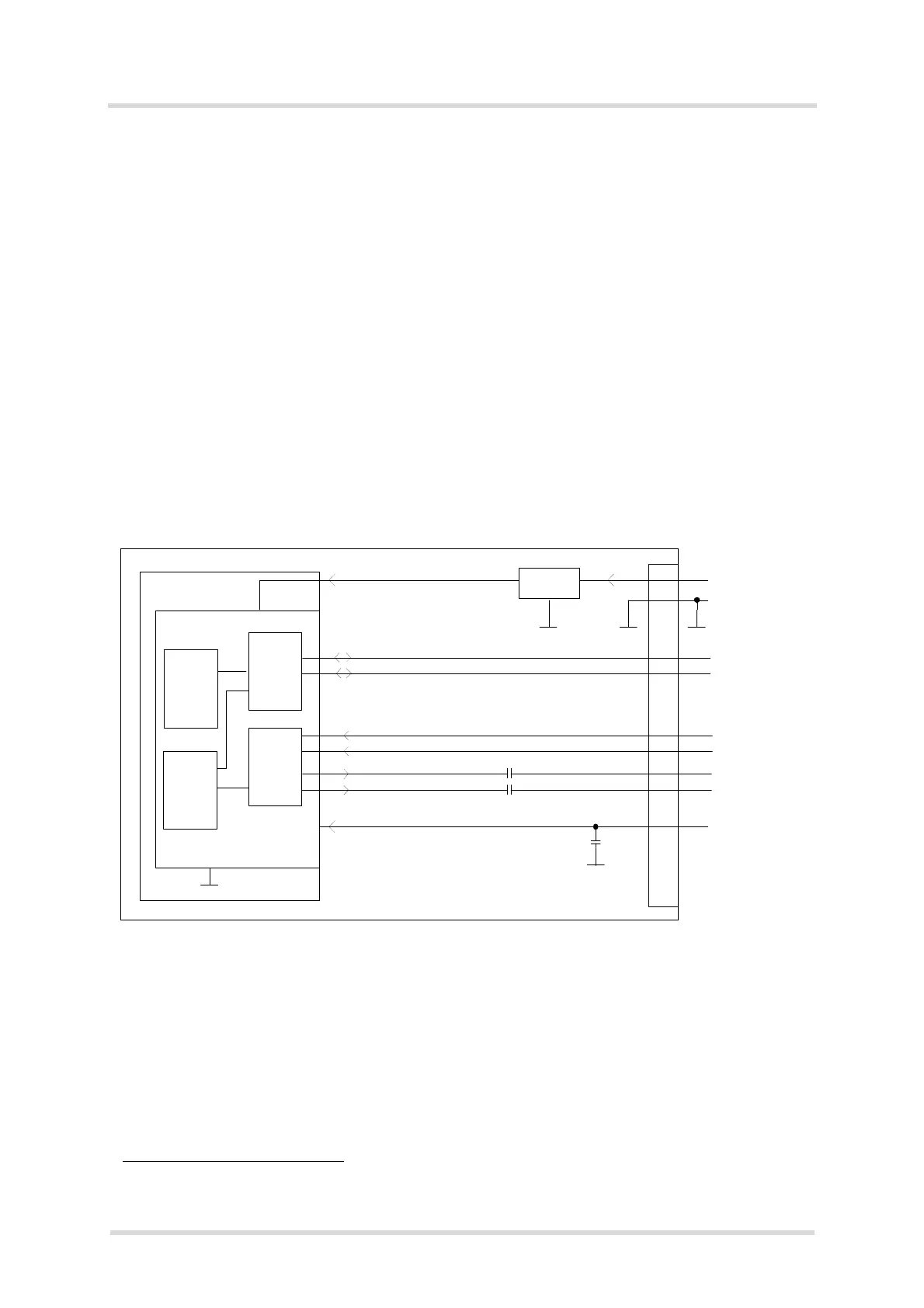
Figure 2: USB circuit
To properly connect the module's USB interface to the external application, a USB 3.0 or 2.0
compatible connector and cable or hardware design is required. Furthermore, the USB modem
driver distributed with ALAS5 needs to be installed.
1. The specification is ready for download on http://www.usb.org/developers/docs/
BATT+
USB_DP
c)
lin. reg.
GND
Module
Detection only
VUSB_IN
b)
USB part
a)
a)
All serial (including R
S
) and pull-up resistors for data lines are implemented .
USB_DN
c)
c)
If the USB interface is operated with super or high speeds, it is recommended to take special care routing the data
lines. Application layout should implement a differential impedance of 90 ohms for proper signal integrity .
VBUS
1µF
b)
Since VUSB_IN is used for detection only it is recommended not to add any further blocking capacitors on
the VUSB_IN line.
USB_SSRX_N
c)
USB_SSRX_P
c)
USB_SSTX_N
c)
USB_SSTX_P
c)
USB_SS
_PHY
USB_HS
_PHY
USB 2.0
Controller
USB 3.0
Controller
2.0
2.0
3.0
100nF
100nF

 Loading...