Cinterion
®
ALAS5 Hardware Interface Overview
2.1 Application Interface
32
ALAS5_HIO_v00.030a 2019-04-01
Confidential / Preliminary
Page 21 of 50
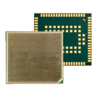
Figure 6: First UICC/SIM/USIM interface
The total cable length between the SMT application interface pads on ALAS5 and the pads of
the external SIM card holder must not exceed 100mm in order to meet the specifications of
3GPP TS 51.010-1 and to satisfy the requirements of EMC compliance.
To avoid possible cross-talk from the CCCLKx signal to the CCIOx signal be careful that both
lines are not placed closely next to each other. A useful approach is using the GND line to
shield the CCIOx line from the CCCLKx line.
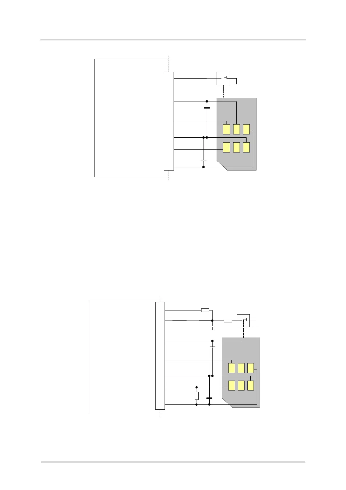
Note: Figure 6 shows how to connect a SIM card holder to the first SIM interface. With the sec-
ond SIM interface some internally integrated components on the SIM circuit will have to be ex-
ternally integrated as shown for the second SIM interface in Figure 7. The external components
at CCIN2 should be populated as close as possible to the signal‘s SMT pad
Figure 7: Second UICC/SIM/USIM interface
Module
open: Card removed
closed: Card inserted
CCRST1
CCVCC1
CCIO1
CCCLK1
CCIN1
SIM /
UICC
1n
220n
SMT application interface
GND
Module
Open: Card removed
Closed: Card inserted
CCRST2
CCVCC2
CCIO2
CCCLK2
CCIN2
SIM /
UICC
1nF
220nF
SMT application interface
GND
VEXT
100pF
22k
2k2
10k

 Loading...