Cinterion
®
ALAS5 Hardware Interface Overview
2.1 Application Interface
32
ALAS5_HIO_v00.030a 2019-04-01
Confidential / Preliminary
Page 19 of 50
2.1.4 Inter-Integrated Circuit Interface
ALAS5 provides an Inter-Integrated Circuit (I
2
C) interface. I
2
C is a serial, 8-bit oriented data
transfer bus for bit rates up to 400kbps in Fast mode. It consists of two lines, the serial data line
I2CDAT and the serial clock line I2CCLK. The module acts as a single master device, e.g. the
clock I2CCLK is driven by the module. I2CDAT is a bi-directional line. Each device connected
to the bus is software addressable by a unique 7-bit address, and simple master/slave relation-
ships exist at all times. The module operates as master-transmitter or as master-receiver. The
customer application transmits or receives data only on request of the module.
The applications’ I
2
C interface can be powered via the VEXT line of ALAS5. If connected to the
VEXT line, the I
2
C interface will properly shut down when the module enters the Power Down
mode.
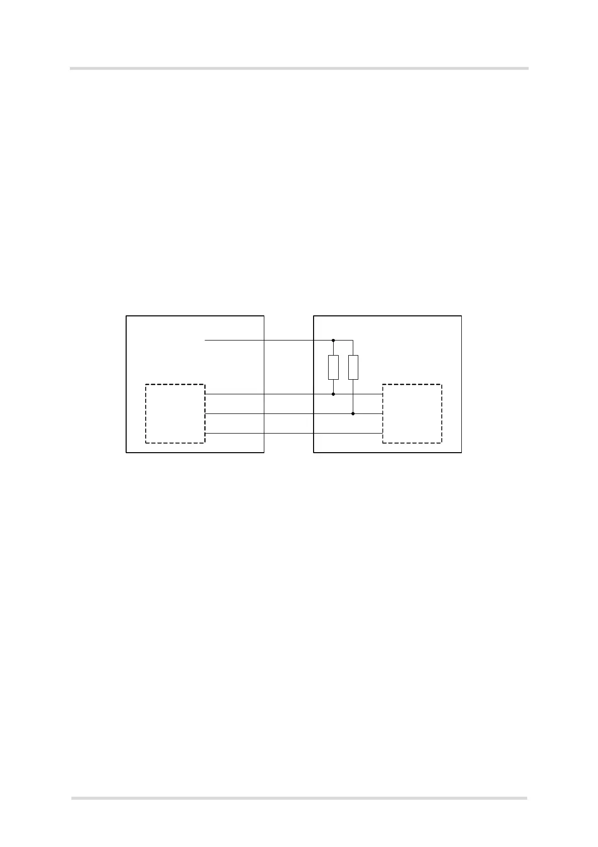
In the application I2CDAT and I2CCLK lines need to be connected to a positive supply voltage
(e.g., VEXT) via a pull-up resistor.
Figure 5: I
2
C interface connected to VEXT
Note: Good care should be taken when creating the PCB layout of the host application: The
traces of I2CCLK and I2CDAT should be equal in length and as short as possible.
I2CCLK
I2CDAT
GND
I2CCLK
I2CDAT
GND
Module Application
VEXT
R pull up
R pull up

 Loading...