Cinterion
®
ALAS5 Hardware Interface Overview
2.3 GNSS Antenna Interface
32
ALAS5_HIO_v00.030a 2019-04-01
Confidential / Preliminary
Page 28 of 50
2.3 GNSS Antenna Interface
In addition to the RF antenna interface ALAS5 also has a GNSS antenna interface. The GNSS
pad’s shape is the same as for the RF antenna interface (see Section 2.2.1).
It is possible to connect active or passive GNSS antennas. In either case they must have 50
impedance. The simultaneous operation of GSM/UMTS/LTE and GNSS is implemented.
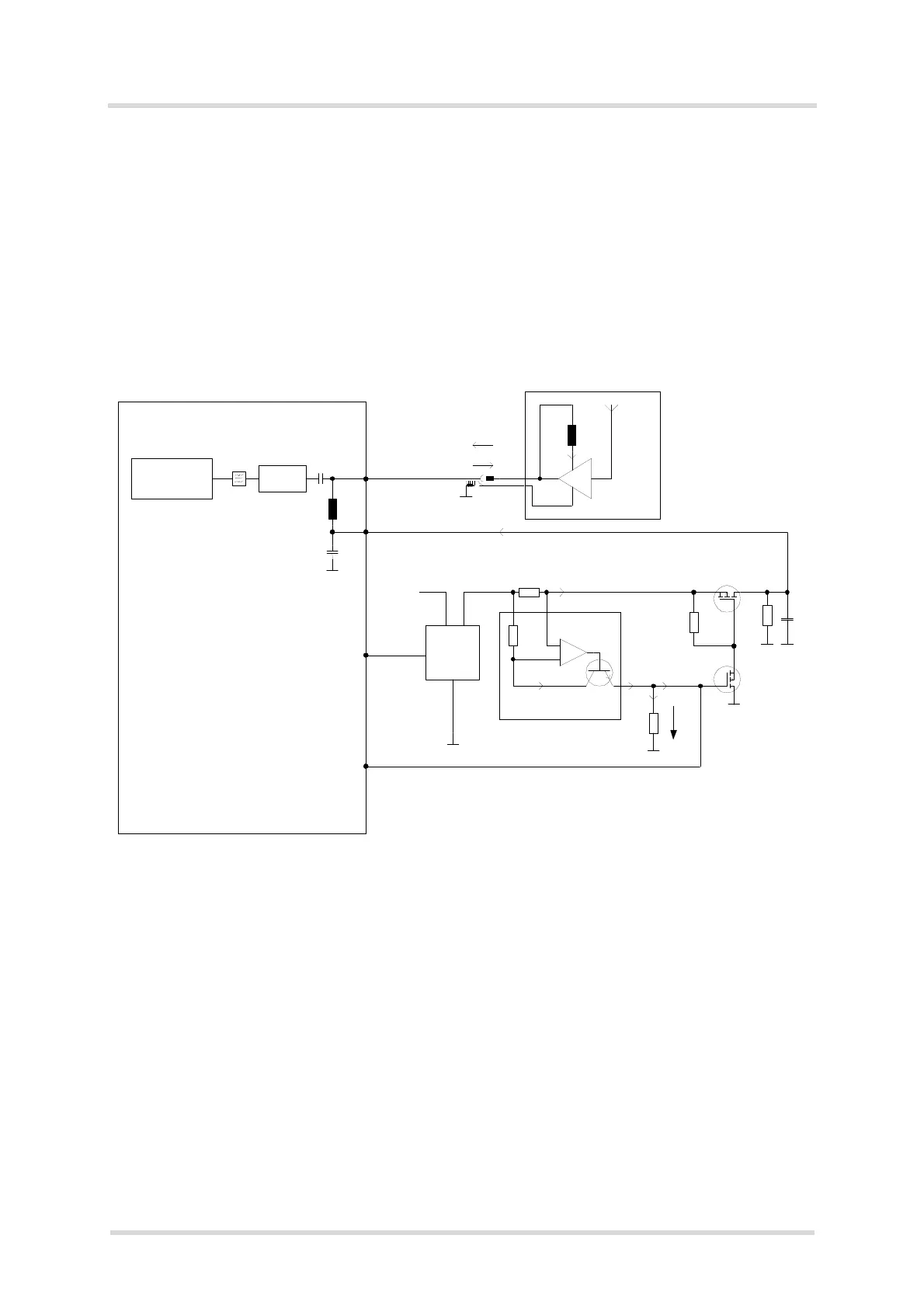
ALAS5 provides the signal GNSS_EN to enable an active GNSS antenna power supply. Figure
11 shows the flexibility in realizing the power supply for an active GNSS antenna by giving a
sample circuit realizing the supply voltage for an active GNSS antenna.
Figure 11: Supply voltage for active GNSS antenna
V
GNSS
Active GNSS
Antenna
DC
+
-
Current Sensor
FAN4010
Is
Rs
(3.2V)
Io
Rv
Io
ADC5_IN
Rg
Ug
GNSS
Receiver
Antenna
Matching
RF
DC
ANT_GNSS_DC
ANT_GNSS
Module
Application:
3k3
1u
10k
ESD
Protection
LNA
100
1R0
LDO
BATT+
EN
IN OUT
GNSS_EN
LP3985IM5-3.2
10k
Si1023X_1
Si1023X_2

 Loading...