Cinterion
®
ALAS5 Hardware Interface Overview
2.1 Application Interface
32
ALAS5_HIO_v00.030a 2019-04-01
Confidential / Preliminary
Page 18 of 50
2.1.3 Serial Interface ASC1
ALAS5 provides a 4-wire unbalanced, asynchronous modem interface ASC1 conforming to
ITU-T V.24 protocol DCE signaling. The electrical characteristics do not comply with ITU-T
V.28. The significant levels are 0V (for low data bit or active state) and 1.8V (for high data bit
or inactive state).
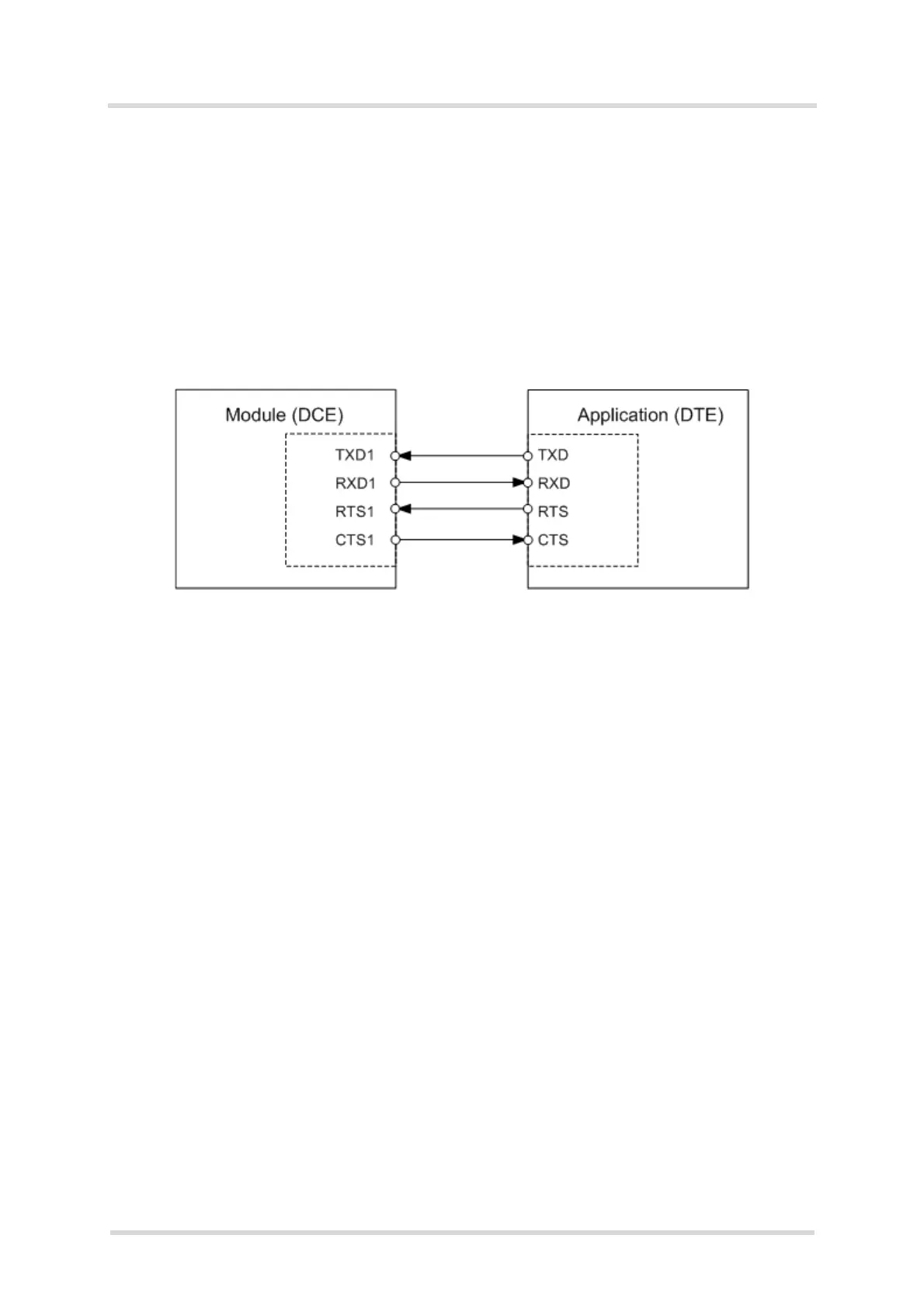
ALAS5 is designed for use as a DCE. Based on the conventions for DCE-DTE connections it
communicates with the customer application (DTE) using the following signals:
• Port TXD @ application sends data to module’s TXD1 signal line
• Port RXD @ application receives data from the module’s RXD1 signal line
Figure 4: Serial interface ASC1
Features
• Includes only the data lines TXD1 and RXD1 plus RTS1 and CTS1 for hardware hand-
shake.
• On ASC1 no RING line is available.
• Configured for 8 data bits, no parity and 1 or 2 stop bits.
• ASC1 can be operated at fixed bit rates from 115,200 bps to 921,600 bps.
• Supports RTS1/CTS1 hardware flow.
• Linux controlled only.

 Loading...