Cinterion
®
Java Terminal Hardware Interface Description
3.16 RF Antenna Interface
40
PLS62T-W_HID_v01 2018-06-20
Confidential / Prelimenary
Page 40 of 91
3.16 RF Antenna Interface
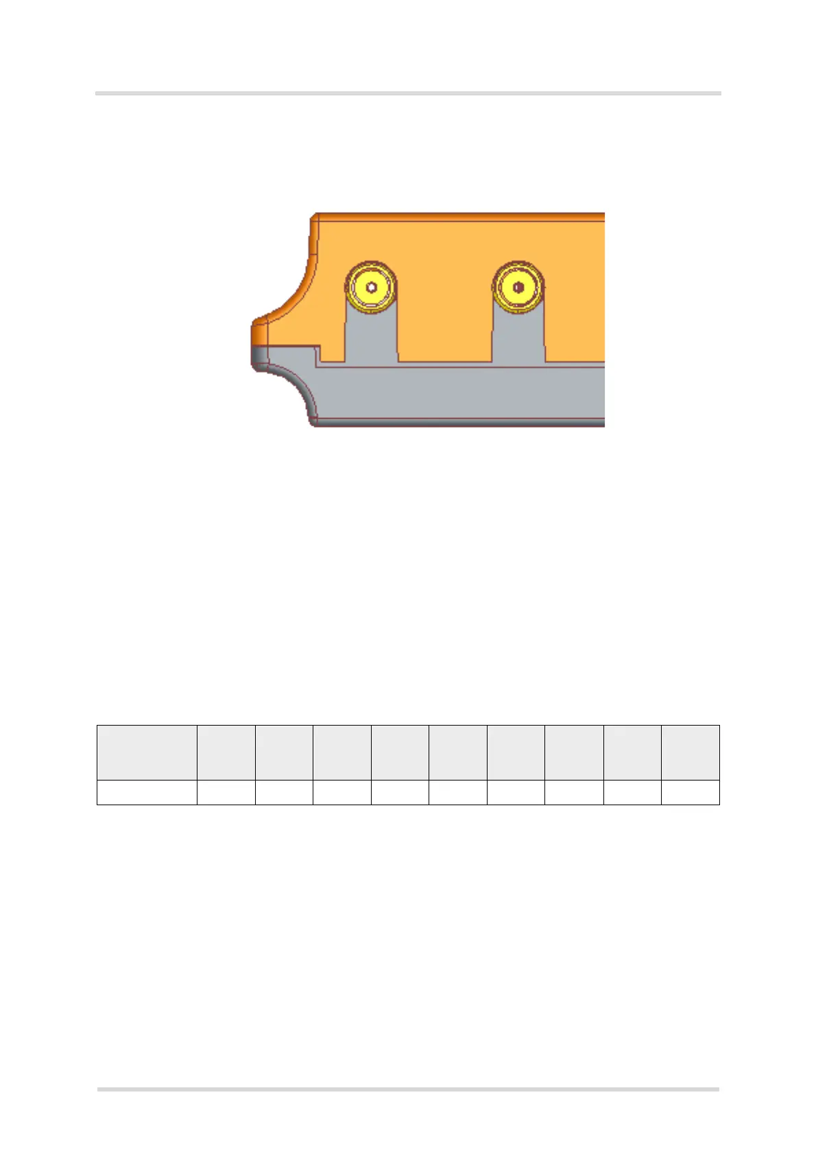
The external RF antennas are connected via the Java Terminal’s female SMA connectors that
is also the antenna reference point (ARP).
Figure 12: Antenna connectors
The system impedance is 50. In any case, for good RF performance, the return loss of the
customer application’s antenna should be better than 10dB (VSWR < 2). Java Terminal with-
stand a total mismatch at this connector when transmitting with maximum RF power.
Additional ESD protection to the antenna connector is provided. No DC voltage must be applied
to the antenna circuit to protect it from damage.
Please note that the terminal should be installed and operated with a minimum distance of
20cm between the antenna connected to the terminal and any human bodies. Also, the trans-
mitter must not be co-located or operating in conjunction with any other antenna or transmitter.
The allowed maximum antenna gain (including cable loss) for stand-alone situation is given be-
low in Table 16.
Table 16: Allowed maximum antenna gain (including cable loss)
Terminal 700
MHz
800
MHz
850
MHz
900
MHz
1700/
2100
MHz
1800
MHz
1900
MHz
2100
MHz
2600
MHz
PL62T-W USB 2.15dBi 2.15dBi 2.15dBi 2.15dBi 2.15dBi 2.15dBi 2.15dBi 2.15dBi 2.15dBi
 Loading...