Cinterion
®
Java Terminal Hardware Interface Description
8.5 Configuring GPIO Directions
90
PLS62T-W_HID_v01 2018-06-20
Confidential / Prelimenary
Page 82 of 91
8.5.1 Configuration using I
2
C Interface
Please refer to Section 8.4 for more information on how to configure the watchdog via I
2
C in-
terface.
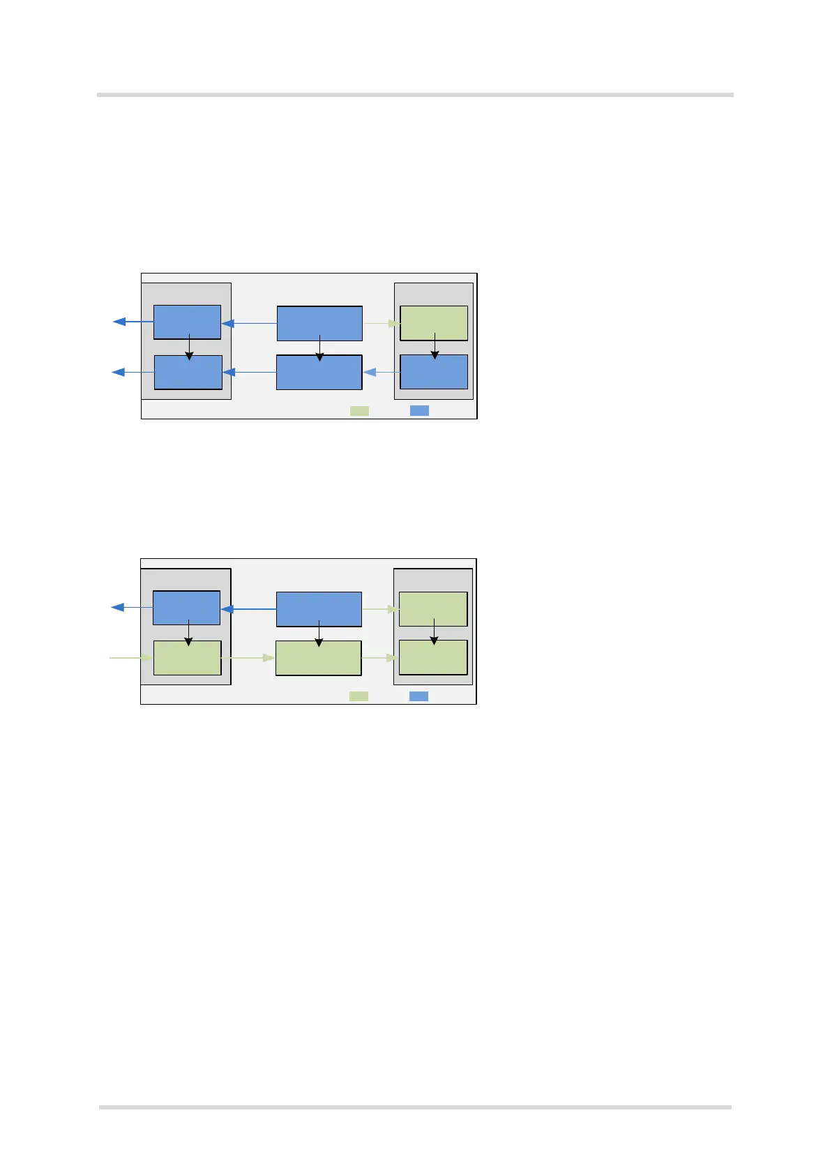
Figure 21 explains the configuration steps required to set the Java Terminal‘s GPIO7 signal di-
rection to OUTPUT (default direction is INPUT):
Figure 21: Setting GPIO direction to OUTPUT via I
2
C interface
Figure 22 shows the configuration steps required to re-set the Java Terminal‘s GPIO7 signal
direction to INPUT:
Figure 22: Setting GPIO direction to INPUT via I
2
C interface
For more information on the AT commands mentioned in the above figures see also [1].
Note: When using a Java MIDlet to set GPIO directions using the I
2
C interface, please allow
for a guard time of at least 500ms between two I
2
C commands.
GPIO connector Java module
Level shifter
GPIO7
GPIO7
Set level shifter to OUTPUT using AT^SSPI and
a specific read/write protocol over I
2
C interface *
Level shifter
GPIO7
GPIO7
Set GPIO7 at Java module to OUTPUT with
GPIO command AT^SCPIN=1,6,1
Now, IO state can be set with AT^SSIO=6,0
Steps:
Voltage level conversion
Java Terminal
= INPUT
= OUTPUT
* See Section 8.4.1.4 for configuration details.
* See Section 8.4.1.4 for configuration details.
GPIO connector Java module
Level shifter
GPIO7
GPIO7
Level shifter
GPIO7
GPIO7
Voltage level conversion
Java Terminal
= INPUT
= OUTPUT
Set GPIO7 at Java module to INPUT with
GPIO command AT^SCPIN=1,6,0
Set level shifter to INPUT using AT^SSPI and
a specific read/write protocol over I
2
C interface *
Now, GPIO7 can be read out with AT^SGIO=6
Steps:
 Loading...