Electrical System
Installation Guidelines For Spark-Ignited Stationary Generators 29
Section 5: Electrical System
General Information
All wiring must be correctly sized, routed, supported, and
connected. All wiring must comply with NEC and local
codes.
The generator uses Customer Connection Interface
(CCI) panels to separate high voltage and customer con
-
trol wiring connections. These two panels are clearly
labeled. Wiring diagrams for each specific unit show con
-
nection points in their corresponding sections. Terminal
boards are labeled and correspond to the same terminal
connections shown in the wiring diagrams. Always use
unit specific wiring diagrams when making wiring connec
-
tions.
NOTE: See Alternator AC Lead Connections.
Connecting Generator Feeder
Conductors
NOTE: Installation and interconnection diagrams are
provided at the back of this manual.
NOTE: All installations must comply with national, state,
and local codes. It is the responsibility of the installer to
perform an installation that will pass final electrical
inspection.
Generator supply connection is made at the generator
disconnect circuit breaker terminals. Conductor sizes
must be adequate to handle the maximum current to
which they will be subjected, based on the 75 °C column
of tables, charts, etc., used to size conductors. Installa
-
tion must comply fully with all applicable codes, stan-
dards, and regulations.
All power cables can enter enclosure through knockouts
provided.
NOTE: Apply corrosion inhibitor to conductors if alumi-
num conductors are used. Carefully wipe away any
excess corrosion inhibitor after tightening terminal lugs.
Tighten terminal lugs to torque values noted on decal
located on the inside of the door. Carefully wipe away
any excess corrosion inhibitor after tightening terminal
lugs.
Proceed as follows to connect generator conductors to
marked terminal lugs in generator:
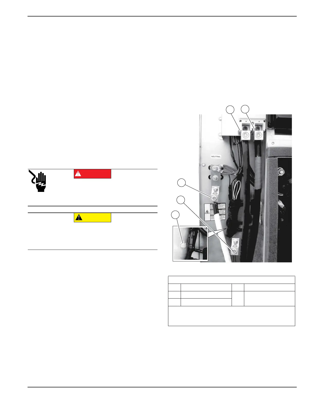
1. See Figure 5-1. Connect generator conductors to
disconnect circuit breaker.
Figure 5-1. High Voltage Connections (Typical)
2. Connect generator neutral to neutral terminal bar.
3. Connect equipment ground to equipment ground
lug.
Electrocution. Turn utility and emergency
power supplies to OFF before connecting
power source and load lines. Failure to do so
will result in death or serious injury.
(000116)
DANGER
(000120)
CAUTION
Equipment damage. Verify all conductors are
tightened to the factory specified torque value.
Failure to do so could result in damage to the
switch base.
Load Wiring Connections
1 E1 4 Ground
2 E2
5
Knock Out Plug
(Cold Weather Kit)
3 Neutral
Notes:
Single-phase installation shown.
See Figure 5-4 for typical control wiring connections.
 Loading...