Electrical System
Installation Guidelines For Spark-Ignited Stationary Generators 31
in both generator and transfer switch. For general infor-
mation regarding wire type, temperature rating, size
range, and wire lug torque specifications, see
Table 5-1
and Table 5-2. Always see NEC tables for specific
requirements.
NOTE: For three-phase applications, use phase rotation
meter to verify generator phase rotation matches rotation
of the utility.
NOTE: For three-phase, delta configured alternators
(voltage code J) and the second leg (N2) must be
bonded to all second legs in the entire system.
See Alternator AC Lead Connections for more infor-
mation.
Control Wiring Connections
The control wire customer connection block is where all
of the control wiring is connected.
IMPORTANT NOTE: All wiring must comply with
NEC, state, and local AHJ requirements. Control wir-
ing shall be installed per the requirements of NEC
Articles 300.3(C) and 725.46. If installing conductors
with different voltage insulation ratings, a 600V rated
electrical sleeve is provided and can be found in the
manual bag.
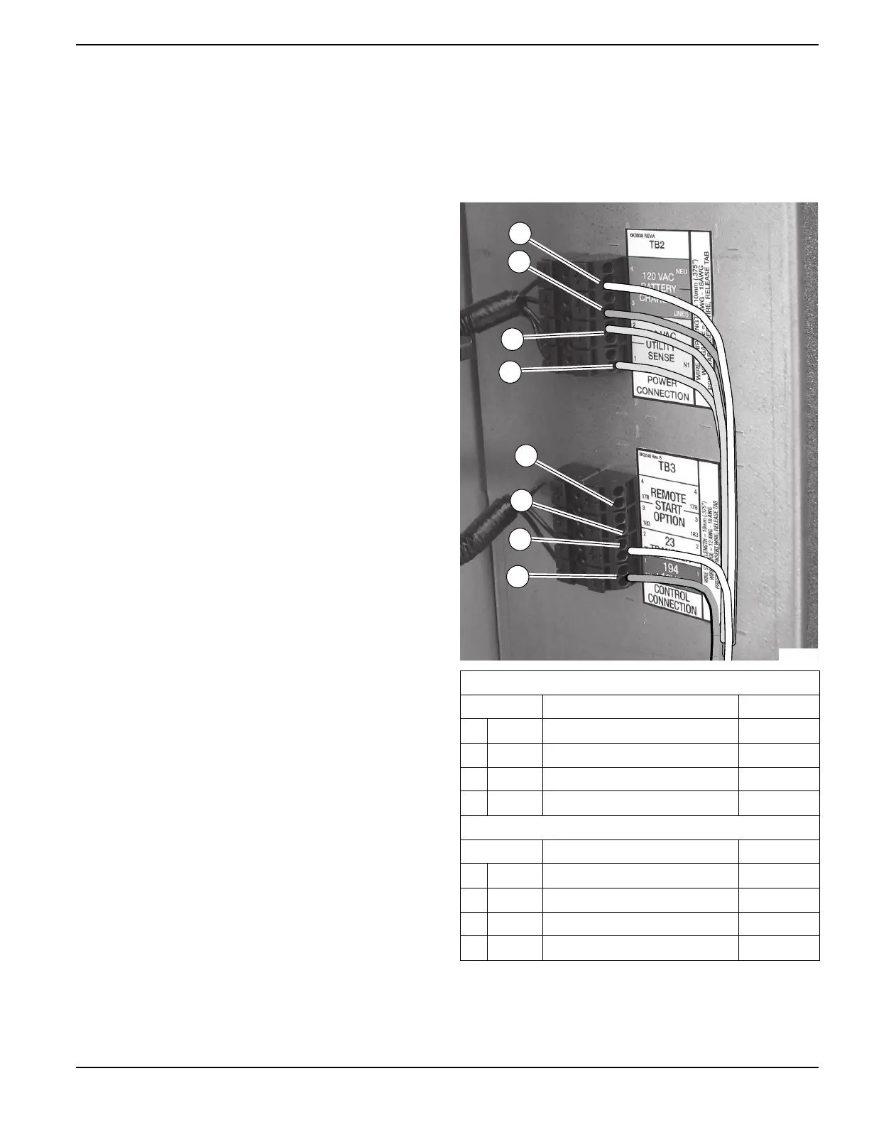
See Figure 5-4. Depending on the system type, control
wiring includes the following. (Wire colors shown for illus-
tration purposes only):
RTS Series Transfer Switch With T1 Fuse/
Connection
NOTE: Control wire customer connections typically use
Class 1 Wiring Methods (verify with AHJ). Always follow
the standards and methods appropriate to the circuits
being wired.
NOTE: T1 is the 120 VAC power supply for the control
panel battery charger. This circuit must be powered
whether transfer switch is in utility or generator mode. If
circuit loses power, control board will generate a warning
(Battery Charge AC Fail).
NOTE: Observe maximum wire size for terminal strip
connections shown in the unit wiring diagram.
(1) For battery charging, connect neutral in TB2 to neutral
in transfer switch. See NOTE below for transfer switches
without T1.
(2) Connect T1 in TB2 to T1 in transfer switch. This is
120 volt supply to the unit's battery charger (normal RTS
transfer switch).
(3) (4) Connect N1, N2 sensing wires in TB2 to N1 and
N2 in transfer switch. These two wires are utility sensing
wires.
(5) (6) Connect 23 in TB3 to 23 in transfer switch. Con-
nect 194 in TB3 to 194 in transfer switch. These are
transfer switch control wires.
NOTE: RTS Series Transfer Switch Without T1 Fuse/
Connection: Use a 120 volt generator protected circuit
from the panel board to power the battery charger circuit
(dedicated 15/20 amp circuit).
Figure 5-4. Control Wiring Connections (Typical)
TB2 Terminal Block
Terminal Function Voltages
1 Neutral Neutral for T1 Battery Charger Neutral
2 T1 Power for T1 Battery Charger 120 VAC
3 N2 Utility Sensing from Transfer Switch 208-277 VAC
4 N1 Utility Sensing from Transfer Switch 208-277 VAC
TB3 Terminal Block
Terminal Function Voltages
A 178 Two Wire Start Control [GTS] 5 VDC
B 183 Two Wire Start Control [GTS] 5 VDC
5 23 Transfer Relay Control Wire 12-0 VDC
6 194 Power for Transfer Relay 12 VDC
 Loading...