Electrical System
30 Installation Guidelines For Spark-Ignited Stationary Generators
Connecting Control Circuit Wires
Control system interconnections may consist of N1, N2,
and T1, and leads 23 and 194. The generator control wir-
ing is a Class 1 signaling circuit. See instruction manual
o
f specific engine generator for wiring connection details.
Recommended wire gauge sizes for wiring depends on
length of wire, as recommended in the following chart:
Exception: Conductors of AC and DC circuits, rated
1,000 volts nominal or less, shall be permitted to occupy
the same equipment, cable, or conduit. All conductors
shall have an insulation rating equal to at least the maxi-
mum circuit voltage applied to any conductor within the
e
quipment, cable, or conduit. See NEC 300.3(C)(1).
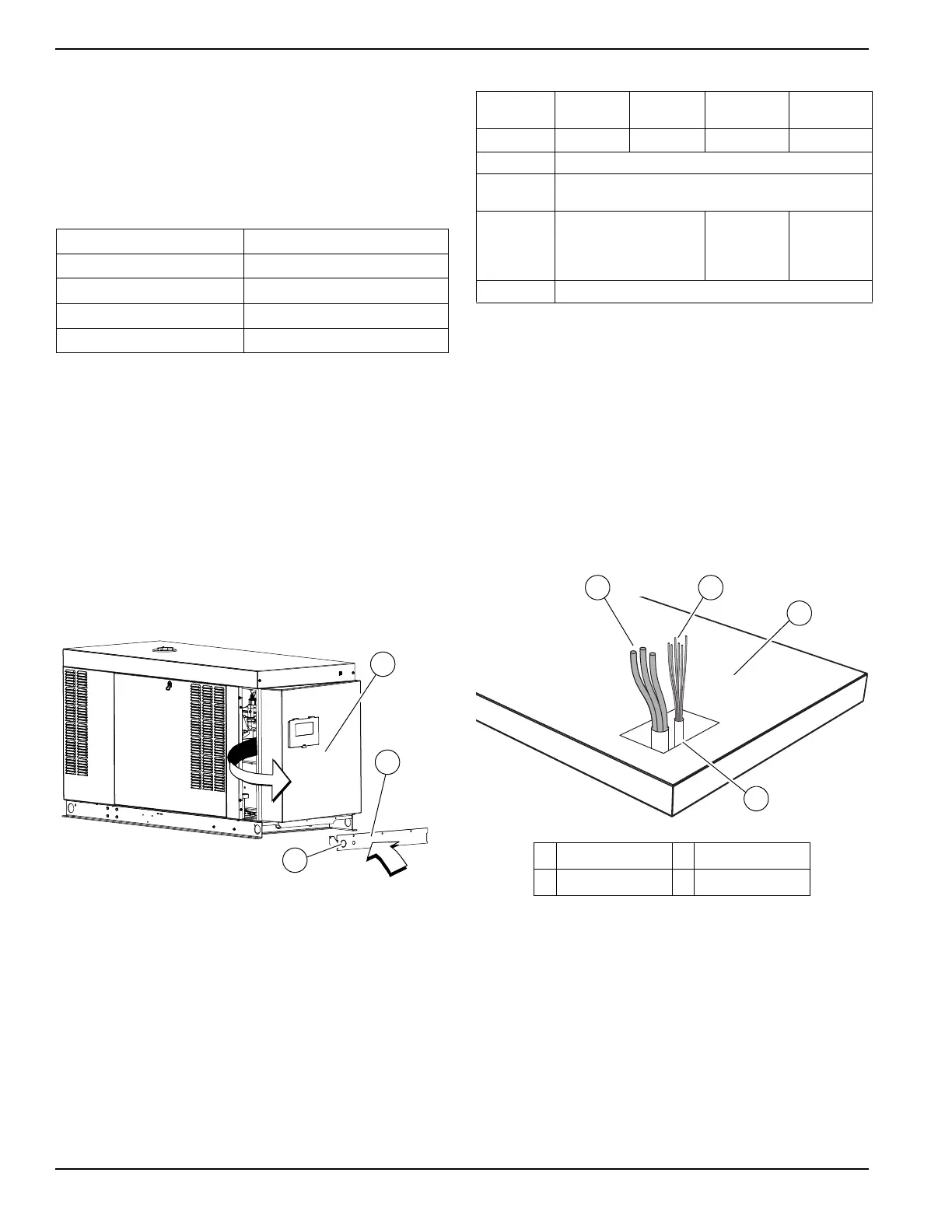
Removing Rear Panel and Stub-Up
Cover
1. See Figure 5-2. Remove six screws with nylon
washers to release rear panel (A) from enclosure.
For
best results, rotate left side of panel outward
away from enclosure before disengaging right side.
Figure 5-2. Remove Rear Panel and Stub-Up Cover
2. Remove f
our screws with nylon washers to release
fascia from control panel.
3. Th
e stub-up cover (B) and five screws with flat
washers are shipped loose and found inside the
enclosure. An optional knock-out (C) is provided.
Table 5-1. Frame Breakers
Frame
Breaker
Generac 225
AF 2 Pole
Generac 225
AF 3 Pole
Generac 400 AF
2 Pole
Generac 400 AF
3 Pole
Range
125A-200A 50A-200A 225A-400A 225A-400A
Wire type
Cu/Al
Wire temp.
rating
167 °F
(75 °C)
Lug AWG
range
(number of
co
nductors)
6-350 kcmil (1) 1/0 -250 kcmil (2)
or
4-600 kcmil (1)
1/0-250 kcmil (2)
or
4-600 kcmil (1)
Lug torque
375
in-lbs
(42.37 Nm)
NOTE: Generac frame breakers are rated at an 80%
continuous load rating. Frame breaker torque specs are
on the breaker data tag.
Typical Load Leads and Control
Wiring in Stub-Up
Figure 5-3 is for reference only. See installation drawings
for unit-specific details.
NOTE: See
300.3(C) and Article 725 in the NEC for rout-
ing of control wires and power wires.
NOTE: A single conduit is permitted.
Figure 5-3. Typical Load Leads and Control Wiring in
Stub-Up
Customer Load Wiring
Customer load wiring consists of single-phase or three-
phase connections between generator main line circuit
breaker (MLCB) and transfer switch. The wiring connects
to lugs E1, E2, (and E3, if three-phase on MLCB), neu-
tral, and equipment ground at generator, and runs to cor-
responding lugs in transfer switch. All load wires, neutral,
an
d ground should be marked and terminated in the cor-
rect lugs in transfer switch. V
erify all wiring is correctly
mounted and terminated at appropriate connection points
Maximum Wire Length Rec
ommended Wire Size
1–115 ft (0.30–35 m) No. 18 AWG
116–185 ft (36–56 m) No. 16 AWG
186–295 ft (57–89 m) No. 14 AWG
296–460 ft (90–140 m) No. 12 AWG
A Load leads C Stub-ups
B Control wiring D Concrete pad
 Loading...