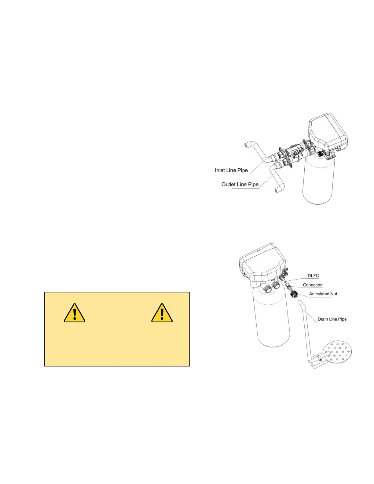
Figure 9-1
8. System Installation
Valve Set-up and Installation - See Page 11-14.
Plumbing Connections
As Figure 9-1 shows; connect inlet pipe, via a 1" NPT female
connector, to the inlet connector of bypass. Repeat steps for
the outlet pipe.
Drain Line Installation
As Figure 9-2 shows; insert drain line with an air gap to the
floor drain. Valve drain hose not supplied.
Figure 9-2
CAUTION
An air gap is required between the drain line
and the drain (sewer). This avoids a syphon
effect and reverse contamination.
Genesis Upflow Valves & Systems Service Manual

 Loading...