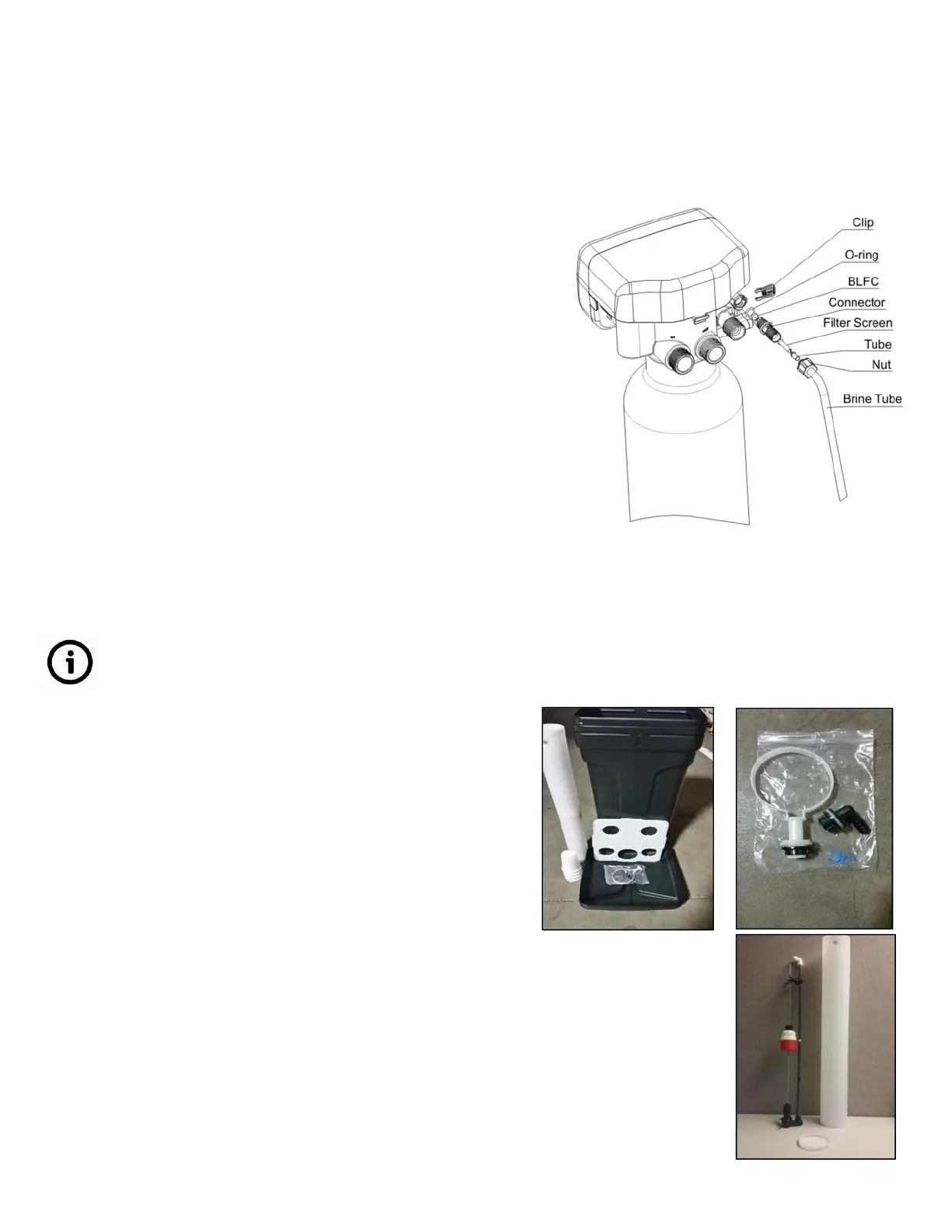
Brine Line Connection
1. As Figure 9-3 shows; slide brine nut onto the 3/8"
brine tubing.
2. Install the filter screen into the ferrule and insert
the ferrule into the end of brine tube.
3. Insert tube into brine connector and tighten brine
nut to the brine connector.
4. Only use stiff walled poly tubing. Drain distance
above softener control should not exceed 20 feet.
If distance is greater than 20ft above control valve
larger (1") pipe diameter should be used. Brine
Tank Installation (also see adder assembly sheet).
Take care to not crimp or plug the brine line or drain line.
Figure 9-3
Brine Tank Installation
1. Unpack brine tank components
• Brine tank standoff with nut and washer
• Overflow elbow with nut and washer
• Optional quick connect clips
2. Open brine well and remove float. Ensure the
inside of the tank and brine well are free of debris.
Genesis Upflow Valves & Systems Service Manual
 Loading...