5
1. Plug the operator into a properly grounded
electrical outlet.
2. Check Safe-T-Beam® alignment (Fig. 6-3).
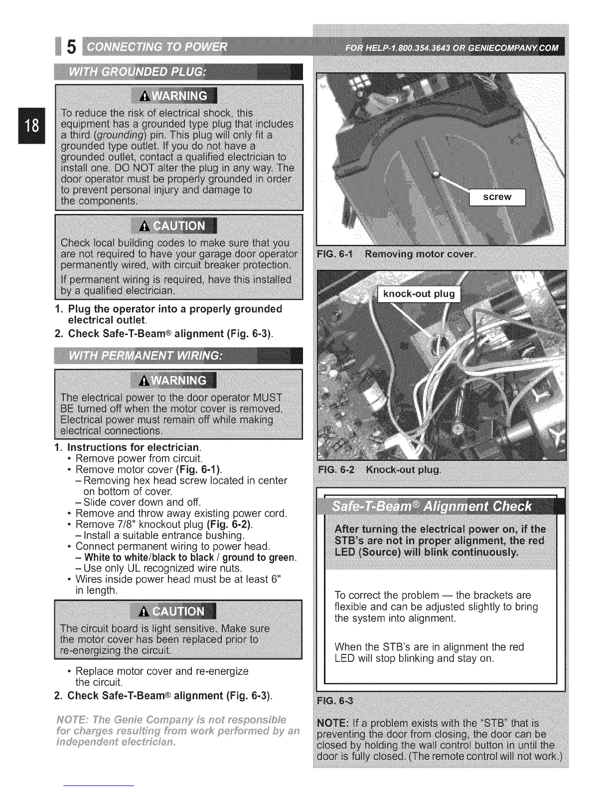
1. instructions for electrician.
• Remove power from circuit.
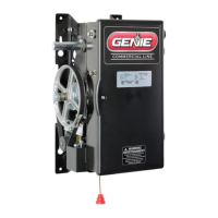
• Remove motor cover (Fig. 6-1).
-Removing hex head screw located in center
on bottom of cover.
-Slide cover down and off.
• Remove and throw away existing power cord.
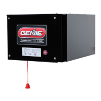
• Remove 7/8" knockout plug (Fig. 6-2).
-install a suitable entrance bushing.
• Connect permanent wiring to power head.
- White to white/black to black / ground to green,
-Use only UL recognized wire nuts.
• Wires inside power head must be at least 6"
in length.
• Replace motor cover and re-energize
the circuit.
2. Check Safe-T-Beam® alignment (Fig. 6-3).
NOT_!: _7e OenFe Co£ p_:_ny;s_no f"espo_,_s/;Ise
m@penden_ eh;_,c_,fc_n,
To correct the problem -- the brackets are
flexible and can be adjusted slightly to bring
the system into alignment.
When the STB's are in alignment the red
LED will stop blinking and stay on.
 Loading...