The GNSS receiver has a microSD card slot fitted as standard. A microSD card can be inserted
and removed.
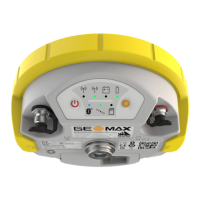
2.4 Instrument Components
a TNC-connector for external UHF
antenna, only for models with UHF
radio
b Battery compartment with
microSD and SIM card slot
c Keyboard with LEDs,
ON/OFF button and Function button
d Serial, USB and power port
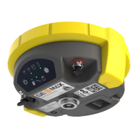
e Antenna Reference Plane (ARP) is
where the instrument heights are
measured to.
2.5 Pin Assignments
Pin Signal Name Function
1 USB_D+ USB data line
2 USB_D- USB data line
3 GND Signal ground
4 RxD RS232, receive data
5 TxD RS232, transmit data
6 ID Identification pin
7 GPIO RS232, general-purpose signal
8 PWR Power input, 10.5 V-28 V
9 NC Not used
10 NC Not used
10 pin LEMO EEG. 1B. 310. CLNP
2.6 The Antenna Reference Plane, ARP
The Antenna Reference Plane:
•
is where the instrument heights are measured to.
•
is where the phase centre variations refer to.
•
varies for different instruments.
The ARP for the GNSS receiver is shown in the diagram.
a The Antenna Reference Plane is the underside
of the thread.
Memory device
GNSS receiver compon-
ents
Pin assignments for serial,
USB and power port
Plug type
Description
ARP for GNSS receiver
Description of the System 15
 Loading...