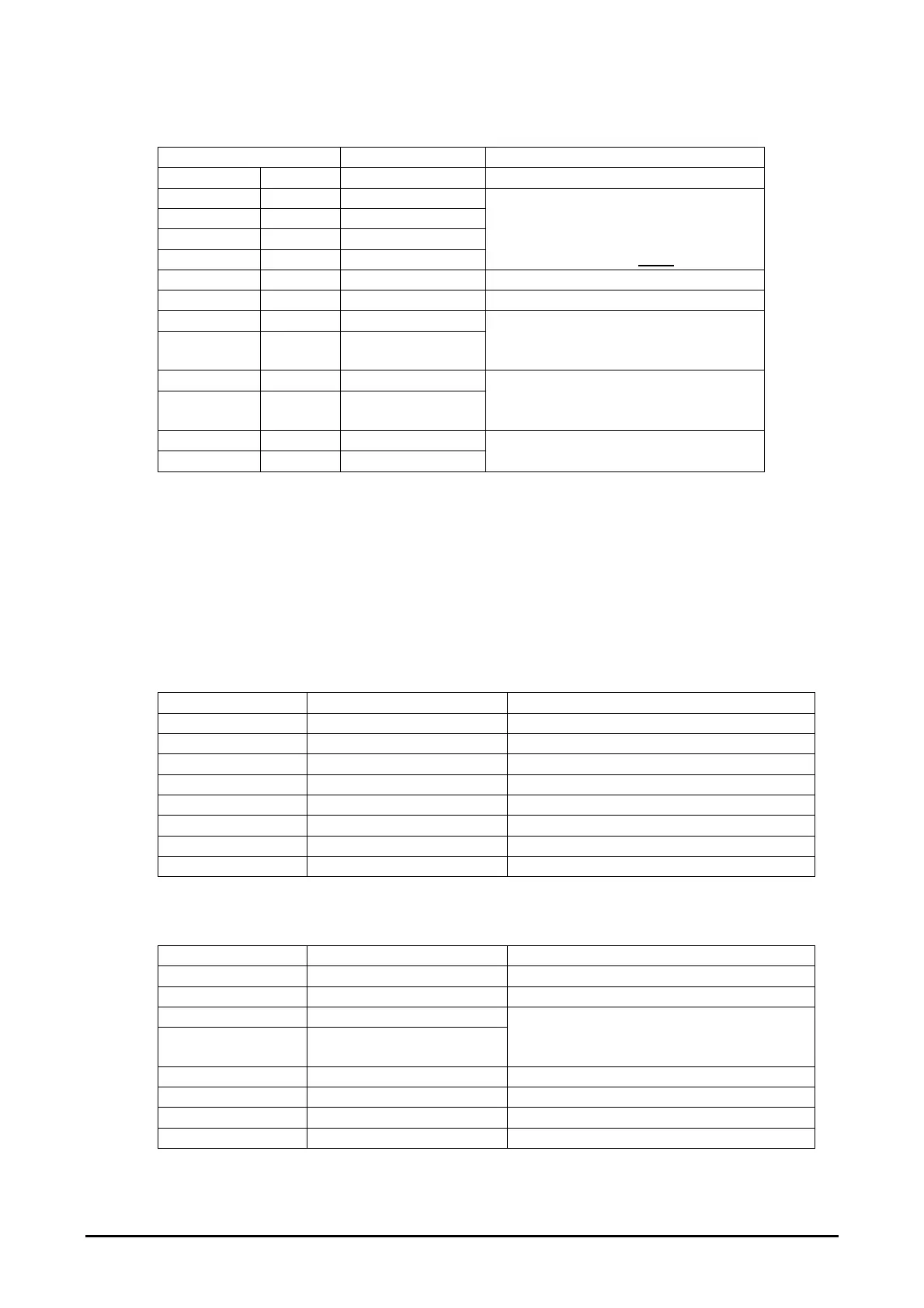
4.6.3.5. P5: Power input
Pin connection Signal name Rating / connection
9 & 12kW 22kW
A1 A1 L1
A2 B1 L2
A3 C1 L3
Frame Frame PE
Mains supply input, for ratings see
Table 6
L1-L3 connections NOT
SELV
B1 F1
B2 F2
B3 F3 Auxiliary_n/o
B4 F4 Auxiliary_n/o_rtn
‘Volt free’ auxiliary n/o contact
output. Contact rating 5A @
24Vdc / 120Vac
B5 F5 Auxiliary_n/c
B6 F6
Auxiliary_n/c_rtn
‘Volt free’ auxiliary n/c contact
output. Contact rating 5A @
24Vdc / 120Vac
B7 F7 Chiller_OK
B8 F8 Chiller_OK_rtn
‘Volt free’ contact input from chiller
4.6.3.6. Protective Earth terminal
An M6 stud is provided on the rear of the
e
-Brick housing to permit Protective Earth (PE)
bonding during installation. Note that the mains supply earth is through P5.
4.6.3.7. P6: Communication port (in)
P6: HMI (Master)
Pin connection Signal name (Master) Rating / connection
1 24V 24V output to HMI
2 0V 0V output to HMI
3 RS485A RS485 bus
4 RS485B RS485 bus
5 KEY No connection
6 5V_control No connection
7 N/C No connection
8 RS485_rtn RS485 Screen
P6: Communications port (Slave, in)
Pin connection Signal name (Slave) Rating / connection
1 RS485A RS485 bus || P2-1
2 RS485B RS485 bus || P2-2
3 E-stop
4 E-stop_rtn
‘Volt free’ contact input from E-stop
output on previous master / slave
e
-
Brick.
5 N/C No connection
6 N/C No connection
7 N/C No connection
8 RS485_rtn RS485 Screen
GEW UV
e
-Brick installation and operating manual 27 of 49
 Loading...