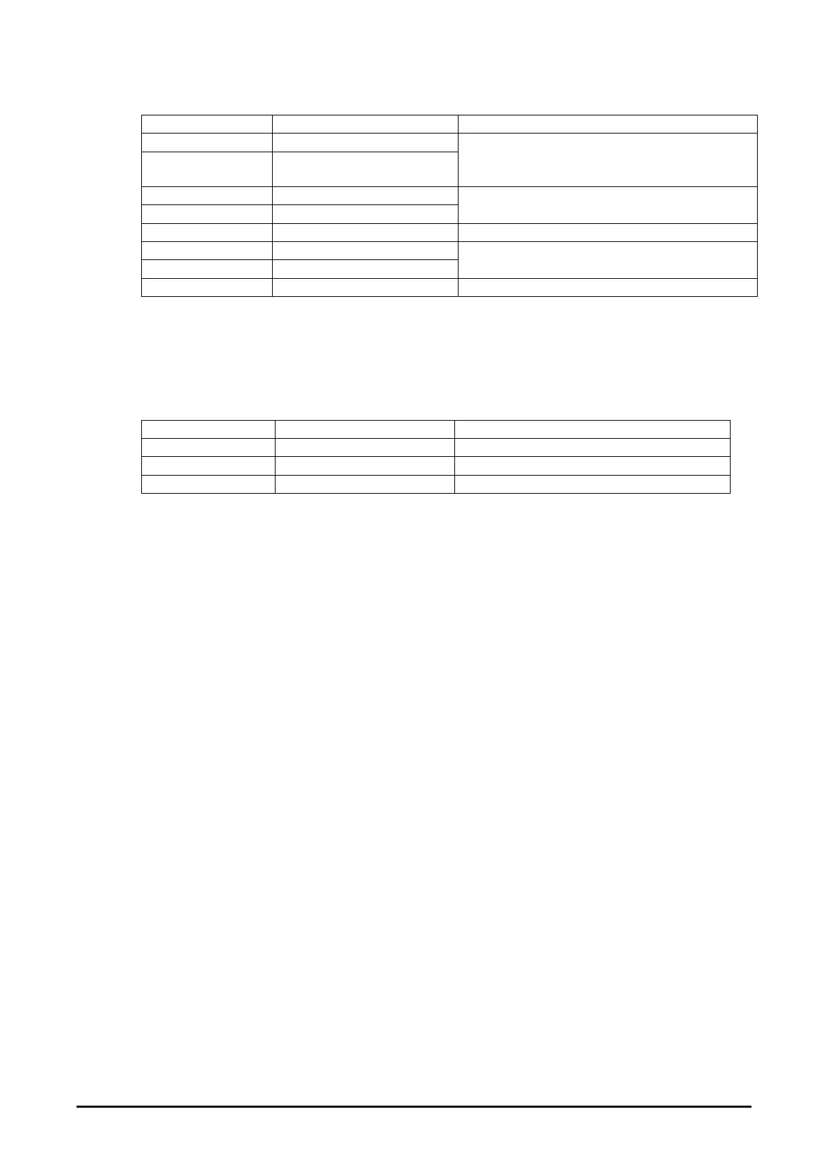
4.6.3.8. P7: System fan interface
Pin connection Signal name Rating / connection
1 Fan_healthy
2 Fan_healthy_rtn
‘Volt free’ contact input from fan overload
auxiliary
[Also available on P1]
3 Fan_start out
7 Fan_start_rtn
24VDC relay output to drive fan contactor
coil. [Also available on P1]
4 KEY Polarising key, no connection
5 Frame_safety_switch
6 Frame_safety_switch_rtn
‘Volt free’ contact input from optional
frame safety switch
8 N/C No connection
4.6.3.9. P8: Profibus interface
Where an
e
-Brick is supplied with an internal Profibus interface, connection to the
external system is made by a standard 9 way ‘D’ type connector (not shown in Figure 7).
Pin connection Signal name (Slave) Rating / connection
1 Profibus_A Profibus network
3 Profibus_B Profibus network
8 RS485_rtn RS485 Screen
GEW UV
e
-Brick installation and operating manual 28 of 49